Example of a Force Function Program
The following describes an example of a simple operation in combination with the force functions.
CAUTION
The parameters described in the example are reference values.
Please note that relatively stable parameters are used, but in some operating conditions, the operation may not succeed or there may be vibrations in the motion, in which case the parameters may need to be adjusted. note that
In addition, slow stable parameters are used for convenience of explanation. For high-speed operation, adjusting the parameters is required.
Pressing Operation
The following describes an example of a program to perform a pressing operation in a constant direction with a target force.
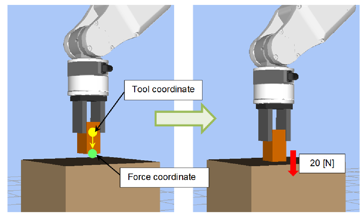
The example operation is to move a workpiece to the position 10 [mm] above the contact position and use the force control function to press the workpiece held by the hand against the worktable with a force of 20 [N].
At the same time, the force trigger function is used to monitor excessive force (100 [N] or more) during the operation, and detecting excessive force causes an error to occur.
Furthermore, when the force motion restriction function is used to operate an unexpected movement (20 [mm] or more) during the operation, the robot will stop operating as an abnormal state in which the worktable does not exist.
Furthermore, the force monitor function is used to measure the Force Sensor values after the operation is completed and also measure the maximum force applied during the operation.
The tool coordinate system is set in the hand tip, and the forward direction of the hand is the Tlz axis direction.
Sample Program
Function PressSample_Main
  Real rVar(8)
  Integer iVar
  Motor On
  Go P0                                 ' Go to the operation start position
  PressSample_PropertySetting           ' Set the property
  FSet FS1.Reset                        ' Reset the Force Sensor
  Trap 1, FT1 Call PressSample_EHandle  ' Start monitoring excessive force
  FSet FM1.PeakForceClear, True, True, True, False, False, False, True, False
    ' Start calculating the peak value
  Till FMR1                             ' Set the motion aborting condition for when the robot moves outside the expected range
  FCKeep FC1 Till, 10                   ' Execute the force control function for 10 seconds
  Print "Motion End"
  FGet FM1.Forces, rVar()               ' Get the Force Sensor value
  Print "Force Fz:", rVar(FG_FZ), ", Fmag:", rVar(FG_FMAG)
  FGet FM1.PeakForces, rVar()           ' Get the peak value
  Print "PeakForce Fz:", rVar(FG_FZ), ", Fmag:", rVar(FG_FMAG)
  FGet FMR1.Triggered, iVar             'Get result of movement restriction
  If iVar = True Then                   'If restricted, display the Overrun error
    Print "Overrun Error"
  EndIf
Fend

Function PressSample_PropertySetting
  FSet FCS1.Position, 0, 0, 30          ' The origin of the force coordinate system is Z30 mm
  FSet FCS1.Orientation, FG_TOOL        ' The orientation is aligned with the tool coordinate system

  FSet FC1.CoordinateSystem, FCS1       ' Specify the defined force coordinate No. 1
  FSet FC1.Enabled, False, False, True, False, False, False
    'Enable the force control function only for the Fz direction.
  FSet FC1.Fz_TargetForce, -20          ' Pressing of 20 N
  FSet FC1.Fz_Spring, 0                 ' The spring value is 0
  FSet FC1.Fz_Damper, 10                ' The damper value is 10
  FSet FC1.Fz_Mass, 10                  ' The mass value is 10

  FSet FT1.ForceSensor, 1               ' Specify Force Sensor No. 1
  FSet FT1.CoordinateSystem, FCS1       ' Specify the defined force coordinate No. 1
  FSet FT1.TriggerMode, FG_FORCE        ' Monitor the force
  FSet FT1.Fmag_Axes, FG_XYZ
  FSet FT1.Enabled, False, False, False, False, False, False, True, False
    'Enable only Fmag
  FSet FT1.Fmag_Polarity, FG_OUT        ' Trigger detects when the value falls outside the threshold range
  FSet FT1.Fmag_Levels, 0, 100          ' The range of Fmag is 0 to 100

  FSet FM1.ForceSensor, 1               ' Specify Force Sensor No. 1
  FSet FM1.CoordinateSystem, FCS1       ' Specify the defined force coordinate No. 1

  FSet FMR1.TriggerMode, FG_REL_TOOL    ' Specify tool relative mode
  FSet FMR1.PosEnabled, False, False, True, False, False
    ' Enable only Z direction
  FSet FMR1.PosZ_Levels, -20, 20        ' The Z range is -20mm to 20mm
  FSet FMR1.PosZ_Polarity, FG_OUT       ' Enable the restriction when the value falls outside the threshold range
  FSet FMR1.ForceSensor, 1              ' Specify Force Sensor No. 1
  FSet FMR1.CoordinateSystem, FCS1      ' Specify the defined Force coordinate No. 1
Fend

Function PressSample_EHandle
  Real rVar(8)
  FGet FM1.PeakForces, rVar()           ' Get the peak value
  Print "Error Handle"
  Print "PeakForce Fz:", rVar(FG_FZ), ", Fmag:", rVar(FG_FMAG)
  AbortMotion All                       ' Abort the robot motion and put it into an error state
Fend
Description
- Executing the PressSample_Main function moves the robot to the operation start position.
- Call PressSample_PropertySetting and execute the settings of the properties.
However, the settings of the properties can also be configured beforehand in Force Editor in the GUI. In this case, there is no need to call the PressSample_PropertySetting. - Set the force coordinate object. For the force coordinate system, specify the Z30 [mm] position in the example to specify the workpiece edge position in the tool coordinate system. The orientation is the same as the orientation of the tool coordinate system.
- Set the force control object. Specify FCS1 set as the coordinate system in which the force control function is executed. Specify a negative value for the target force, as the pressing operation is performed in the positive FZ direction. Set the spring, damper, and mass values. "0" is set in Spring in this example, so the robot does not have a virtual spring and continues to move until the target force is achieved. In addition, stable parameters are used for Damper and Mass. For faster operations, adjust these values by decreasing them gradually. However, decreasing the values increases the overshoot of the force.
- Set the force trigger object. Specify the Force Sensor number to be used and the coordinate system in which the force trigger function is executed. Specify a force in the TriggerMode property to monitor excessive force. Specify X, Y, and Z, as the composite force to be monitored is calculated using all Fx to Fz. Specify 0 to 100 [N] for the Fmag range to set 100 [N] for the excessive force, and configure to monitor whether the value falls outside this range.
- Set the force monitor object. Specify the Force Sensor number for measurement and the coordinate system.
- Set the force motion restriction object. The robot moves in the + Z direction of the tool coordinate system according to the settings in (a) and (b). In the example, if the robot moves more than 20 mm, the setting to detect that there is no object to press is performed. Specify the tool relative mode for TriggerMode to detect the moving distance of the tool coordinate system. In Enabled, enable only PosZ to detect the Z direction. Specify -20 to 20 [mm] as the range in the Z direction, and set to monitor whether it is outside this range.
- Reset the Force Sensor before using the force functions.
- Specify the force trigger object in Trap and execute the force trigger function. Thus, excessive force is monitored.
- Set the force motion restriction object to the Till condition.
- Calculation of the peak value of the force applied during the operation starts.
- Execute the force control function for 10 seconds. During execution, if the force motion restriction condition specified in the Till condition is met, the operation is aborted.
- Get and display the current and peak values of the Force Sensor. In this example, only the values are displayed. These values can be used to determine the pass or fail of the operation and branch the process.
- Get the result of force motion restriction. In this example, if the condition is met, an error is only displayed as an overrun, but recovery processing etc. can also be performed.
- If excessive force is detected during the operation, the program is aborted and the PressSample_EHandle function is interrupted and executed. The peak value applied during the operation is acquired and displayed, the robot motion is aborted, and an error state is entered. In this example, an error state is entered, but processes in the event of an error, such as a retry, also can be executed.