Standard environment specification (LS14-C***S)
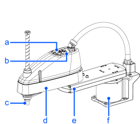
| Symbol | Description |
|---|---|
| a | LED lamp |
| b | Joint #3 #4 Brake release switch |
| c | Shaft |
| d | Arm #2 |
| e | Arm #1 |
| f | Base |
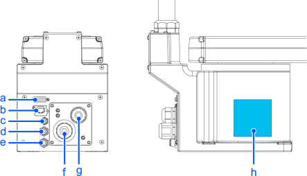
| Symbol | Description |
|---|---|
| a | User connector (15-pin D-sub connector) |
| b | Ethernet connector |
| c | Fittings for ⌀4 mm pneumatic tube |
| d | Fittings for ⌀6 mm pneumatic tube (blue) |
| e | Fittings for ⌀6 mm pneumatic tube (white) |
| f | Power cable |
| g | Signal Cable |
| h | Signature label (Serial No. of Manipulator) |
KEY POINTS
- The brake release switch affects both Joints #3 and #4. When the brake release switch is pressed in emergency mode, the brake for both Joints #3 and #4 are released simultaneously.
- While the LED lamp is on, current is being applied to the Manipulator. Performing any work with the power ON is extremely hazardous and may result in electric shock and/or malfunction of the robot system. Make sure to turn OFF the controller power before maintenance work.
Standard environment specification (LS14-C***S)
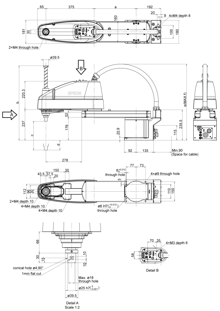
| LS14-C602S | LS14-C603S | LS14-C702S | LS14-C703S | LS14-C802S | LS14-C803S | |
|---|---|---|---|---|---|---|
| a | 225 | 225 | 325 | 325 | 425 | 425 |
| b | 577 | 677 | 577 | 677 | 577 | 677 |
| c | 200 | 300 | 200 | 300 | 200 | 300 |
| d | 53 | 153 | 53 | 153 | 53 | 153 |
| e | 588 | 588 | 606 | 606 | 615 | 615 |
| f | 615 | 615 | 651 | 651 | 682 | 682 |