Digital I/O Interface
The operation of the flexible feeder can be controlled from external devices such as PLCs via a digital I/O interface. For details, refer to the manual below.
"Epson Feeder Configurator Manual"
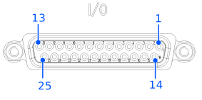
| Pin | Name | Input/Output | Function | Description *2 |
|---|---|---|---|---|
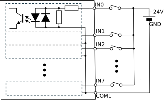
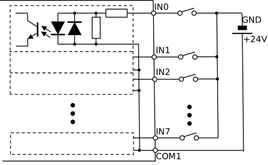
| 1 | COM1 | - | IN0 - IN7 COM | Input Common: Both NPN and PNP connections are possible. |
| 2 | IN0 | Input | Select Operation | Select Operation IN0, IN1=00 Feeder vibration operation IN0, IN1=01 Sequence operation IN0, IN1=10 Hopper operation IN0, IN1=11 Purge gate operation |
| 3 | IN1 | Input | ||
| 4 | IN2 | Input | Start Execution | The operation selected in "Select Operation" will begin. However, it will not start while "Stop Execution" is ON. |
| 5 | IN3 | Input | Action/Sequence Selection | Specify the action number or sequence number to be executed by the operation selected in "Select Operation". |
| 6 | IN4 | Input | ||
| 7 | IN5 | Input | ||
| 8 | IN6 | Input | ||
| 9 | IN7 | Input | ||
| 10 | COM2 | - | IN8 - IN15 COM | Input Common: Both NPN and PNP connections are possible. |
| 11 | IN8 | Input | Stop Execution | Stop the operation started by "Start Execution". |
| 12 | IN9 | Input | Part ID | Specifying the part ID |
| 13 | IN10 | Input | ||
| 14 | IN11 | Input | ||
| 15 | IN12 | Input | ||
| 16 | IN13 | Input | Reset | Reset the "Error Code" and "Stopped" outputs. |
| 17 | IN14 | Input | Backlight | Backlight ON/OFF input |
| 18 | IN15 | Input | Priority | When controlling from an external device, this signal must always be turned ON. *3 |
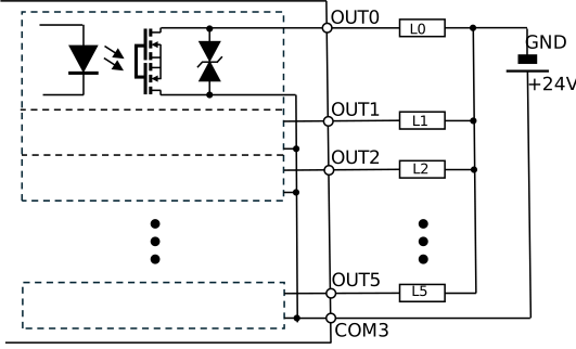
| 19 | COM3 | - | OUT0 - OUT5 COM | Output Common |
| 20 | OUT0 | Output | Ready | ON when stopped, OFF when running. |
| 21 | OUT1 | Output | Action Executing | It turns ON when the operation starts, and turns OFF after a waiting period has elapsed since the operation finished. |
| 22 | OUT2 | Output | Stopped | It turns ON when you stop execution using "Stop Execution". The output is maintained until it is cleared by "Reset". |
| 23 | OUT3 | Output | Error Code | When an error occurs, the type of error is displayed. The output is maintained until it is cleared by "Reset". |
| 24 | OUT4 | Output | ||
| 25 | OUT5 | Output |
*1. The input and output of the digital I/O interface conform to IEC 61131-2 Type-1 digital input and IEC 61131-2 (PLC safety standard) digital output (maximum 0.5A).
*2. For details, refer to the "Epson Feeder Configurator Manual".
*3. When the "Priority" input is turned ON, you cannot start/stop feeder vibration operation via the Ethernet interface. Only via the digital I/O interface is this valid.
Input wiring example 1
Input wiring example 2
Output wiring example 1 (NPN/Sink type)
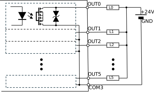
Output wiring example 2 (NPN/Source type)