End Effector
The end effector must be fabricated by customers.
Key Point
For details about mounting screw holes position on end effector side, refer to the following section.
CAUTION
- Design the sensor installation face of the end effector so that the sensor can be completely contacted to the end effector. Also, use the end effector with sufficient rigidity in order to achieve high performance of the sensor.
- When operating the Manipulator with the end effector installed, the end effector may collide with the Manipulator body due to following factors.
- End effector outer diameter /
- Work piece size /
- Force Sensor outer diameter/
- Arm position, etc. When designing the system, be very careful of interference area of the end effector and Force Sensor.
Guidelines of Allowable Moment
The following describes precautions when designing an end effector.
There is an allowable moment on joints of the robot. You need to design the robot not to exceed the limit of the allowable moment of corresponding joints. Allowable moment is calculated as follows.
When the direction of the load and pressing moment are the same:
- Moment [N m]
- = Load mass (mass of the Force Sensor, end effector, and workpiece) [kg]×Gravitational acceleration [m/s2]×axis distance between center of rotation and load's center of gravity [m]+pressing force [N]×axis distance between center of rotation and contact point [m]
When the direction of the load and pressing moment are different:
- Moment [N m]
- = Load mass (mass of the Force Sensor, end effector, and workpiece) [kg]×Gravitational acceleration [m/s2]×axis distance between center of rotation and load's center of gravity [m]−pressing force [N]×axis distance between center of rotation and contact point [m]
Calculation example: Upward (C4: J5)
Procedure for calculating allowable moment which is applied on J5 on C4 series Manipulator when applying 5N upward.
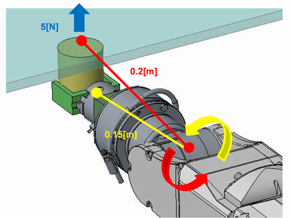
- Moment [N m] applied on J5
- = Load mass (Force Sensor, end effector, workpiece) [kg]×Gravitational acceleration [m/s2]×J5 Distance between center of rotation and gravity center of load [m]+pressing force [N]×J5 Distance between center of rotation and contact point [m]
- = 1[kg]× 9.8[m/s2]×0.15[m]+5[N]×0.2[m]
- = 2.47[N m]
Calculation example: Downward (C4: J5)
Procedure for calculating allowable moment which is applied on J5 on C4 series Manipulator when applying 5N downward.
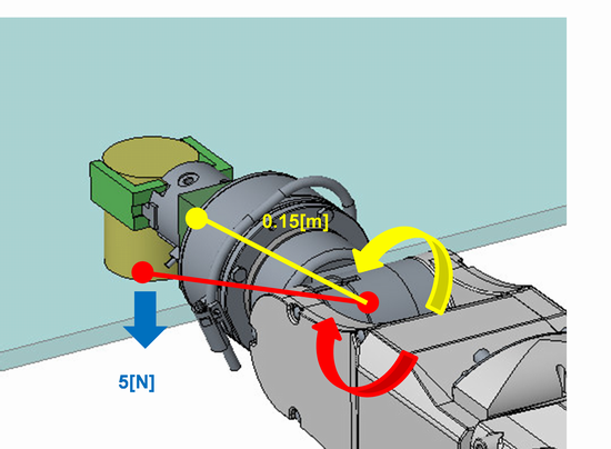
- Moment [N m] applied on J5
- = Load mass (Force Sensor, end effector, workpiece) [kg]×(Gravitational acceleration [m/s2]×(Joint distance between center of rotation and gravity
center of load [m]+pressing force [N]×Joint distance between center of rotation and contact point [m]
- = 1[kg]× 9.8[m/s2]×0.15[m]-5[N]×0.2[m]
- = 0.47[N m]
There is no problem since moment 0.47[N(m] applied on J5 does not exceed the allowable moment 4.41[N(m] of J5.
Perform the same consideration or verification for other joints.
Guidelines for Joint Torque
When application applies a great force or load of end effector/workpiece is heavy, follow the directions shown below and check the joint torque.
Check of Joint Peak Torque
PTRQ can acquire or display the peak torque. (Refer to sample program for usage.)
When PTRQ is "1", problems of security may occur. Make sure to check the PTRQ is less than "1".
Function PTRQ_Check                  'Sample program to acquire and display PTRQ
  Integer i
  Double PT(6)
  Do                                 'Repeat motion part and PTRQ acquisition part
    PTCLR                            'Clear the peak torque
'---Motion part (Example)---Motion part is an example and is described by user
    TLSet 1, XY(0, 0, -49, 0, 0, 0)  'Set tool 1
    Tool 1                           'Specify Tool 1
    Motor On                         'Motor on
    Power High                       'Power high
    Speed 100                        'PTP motion speed setting
    Accel 100, 100                   'PTP motion acceleration setting
    SpeedS 50                        'CP motion speed setting
    AccelS 500, 500                  'CP motion acceleration setting

    Go P1                            'PTP motion to P1
    Go P2 +Z(20)                     'Move to P2+Z20mm
    Move P2

    FSet FC1.Fz_Enabled, True        'Enable force control function only for Fz
    FSet FC1.Fz_Spring, 0            'Spring value is 0
    FSet FC1.Fz_Damper, 10           'Damper value is 10
    FSet FC1.Fz_Mass, 10             'Mass value is 10
    FSet FC1.Fz_TargetForce, -50     'the target force of Fz to -50N
    Wait 0.3                         'Wait for 0.3 s
    FSet FS1.Reset                   'Reset the Force Sensor
    FCKeep FC1, 10                   'Run the force control function for 10 s

    Move P2                          'Move to P2
    Go P2 +Z(20)                     'Move to P2+Z20mm
'-----------------------------------------------------
    For i = 1 To 6                   'Repeat 1 to 6
      PT(i) = PTRQ(i)                'Acquire PTRQ
      Print "PT_J", i, "=", PTRQ(i)  'Display PTRQ
    Next
  Loop
Fend
Overload Rate of Joint
OLRate can acquire or display the overload rate. (Refer to sample program for usage.)
OLRate rises when overload is applied on the joints and falls when overload is no longer applied. Stop as servo error when OLRate keeps rising and becomes "1". Make sure that OLRate does not keep rising. In particular, check the OLRate rising amount of one motion cycle is "0".
Function OLRate_Check                'Program to acquire or display OLRate
  Integer i, j
  Double OLCheck(6), OL(6)
  Do                                 'Repeat motion part and PTRQ acquisition part
'---Motion part (Example)--- Motion part is an example and is described by user
    TLSet 1, XY(0, 0, -49, 0, 0, 0)  'Set tool 1
    Tool 1                           'Specify Tool 1
    Motor On                         'Motor on
    Power High                       'Power high
    Speed 100                        'PTP motion speed setting
    Accel 100, 100                   'PTP motion acceleration setting
    SpeedS 50                        'CP motion speed setting
    AccelS 500, 500                  'CP motion acceleration setting

    Go P1                            'PTP motion to P1
    Go P2 +Z(20)                     'Move to P2+Z20mm
    Move P2                          'CP motion to P2

    FSet FC1.Fz_Enabled, True        'Enable force control function only for Fz
    FSet FC1.Fz_Spring, 0            'Spring value is 0
    FSet FC1.Fz_Damper, 10           'Damper value is 10
    FSet FC1.Fz_Mass, 10             'Mass value is 10
    FSet FC1.Fz_TargetForce, -50     'the target force of Fz to -50N
    Wait 0.3                         'Wait for 0.3 s
    FSet FS1.Reset                   'Reset the Force Sensor
    FCKeep FC1, 10                   'Run the force control function for 10 s

    Move P2                          'Move to P2
    Go P2 +Z(20)                     'Move to P2+Z20mm
-----------------------------------------------------
    For i = 1 To 6                   'Repeat 1 to 6
        If j = 1 Then                'the second cycle or later
            OLCheck(i) = OLRate(i) - OL(i)
              'Acquire OLRate rise amount of one motion cycle
            OL(i) = OLRate(i)        'Acquire OLRate
            Print "OLCheck_J", i, "=", OLCheck(i)
              'Display OLRate rise amount of one motion cycle
        Else                         'For the first cycle
            OL(i) = OLRate(i)        'Acquire OLRate
        EndIf
    Next
    j = 1
  Loop
Fend
Cautions about Wires and Pipes
Force may be applied to the end effector due to the cable which is connected to the end effector or pulling from the pipes. The Force Sensor also detects this force. This force may have bad influence for the operation. Therefore, fix the cables and pipes to the sensor binding part.
Fix the wires and pipes to the sensor binding part to reduce the influence of elastic force or gravity.

Force or torque will be generated when wires or pipes touch to surrounding objects. Fix the wires and pipes so as not to touch surroundings.

Precautions When Handling Heavy Loads or Heavy Objects
When handling heavy loads or heavy objects, the rated load of Force Sensor may be exceeded depending on the operation. Before using, perform a verification in the customer's environment and set the speed and acceleration so that the rated load is not exceeded (Reference: 4. Force Sensor). When the rated load is exceeded during force control operation, the 5548 error will occur.
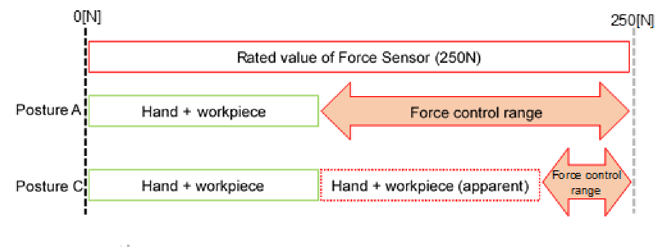
Precautions Involved in Posture Change of Force Sensor
When a posture is greatly changed after resetting Force Sensor, the range of force control may be limited.
The figure below assumes that the Hand attached to the Force Sensor is holding the workpiece (the total weight of the workpiece and Hand is 50[N]) and is moving it from posture A to posture C, in which the J5 axis of posture A is changed by 180°.
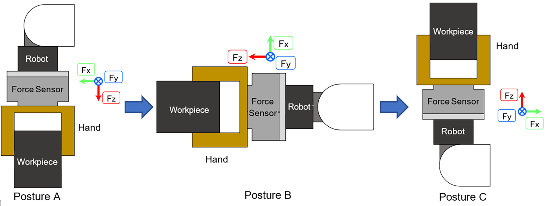
The load applied by each posture to Force Sensor is shown in the table below.
Fx [N] | Fy [N] | Fz [N] | |
|---|---|---|---|
| Posture A | 0 | 0 | 50 |
| Posture B | -50 | 0 | 0 |
| Posture C | 0 | 0 | -50 |
When Force Sensor is reset in the posture A, the output is 0 based on the posture A in the table above. The output values of Force Sensor when the posture A has changed to each posture are shown in the table below.
| Fx [N] | Fy [N] | Fz [N] | |
|---|---|---|---|
| Posture A | 0 | 0 | 0 |
| Posture B | -50 | 0 | -50 |
| Posture C | 0 | 0 | -100 |
In the posture C, the force applied to the sensor is the weight of Hand and a workpiece, but the value output from Force Sensor is twice that. When the Press work is operated in the posture C, Force Sensor originally can control the force of 250[N]. However, since Force Sensor has already been given 100[N], the remaining force is 150[N] and the maximum value that can be controlled by the force is reduced. A 5548 error occurs if the output value of Force Sensor exceeds its rated value during force controlling. Make sure that a program does not exceed the rated range.
For gravity compensation, refer to "Software Coordinate Conversion , Gravity Compensation ".