Wiring of the Force Sensor Cable
The following are recommended wiring examples of the Force Sensor and rough operation ranges of the Manipulator. For actual applications, fix the wiring according to your Manipulator use.
C4 series-S250N
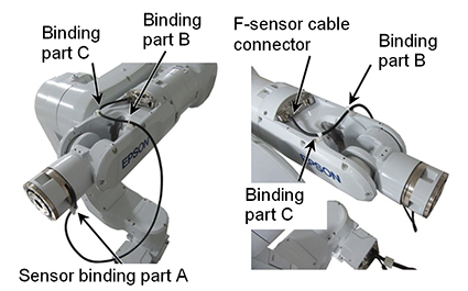
C4 series Manipulator wiring example
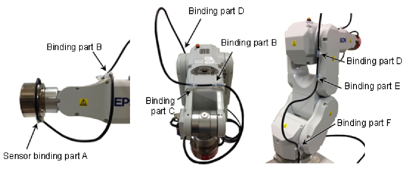
Length of A-B (excess length for rotation of J5 and J6): 400 mm
Adjust the lengths of C-D and E-F according to the Manipulator motion.
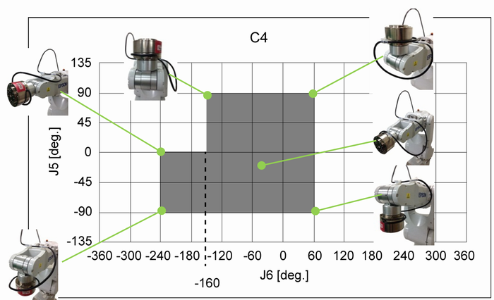
C4 series Manipulator rough operation range
J5 | J6 |
|---|---|
| 0 to 90 deg | -160 to 60 deg |
| -90 to 0 deg | -240 to 60 deg |
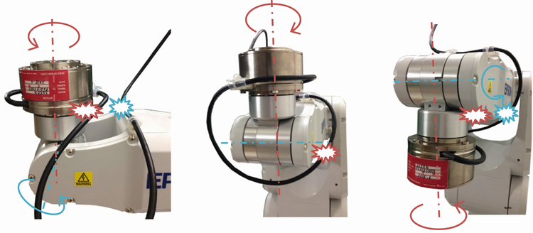
CAUTION
The cables may deform during storage. Caution is required this regard. The cable's bend radius is at least five times larger than the cable diameter (R=30 mm or larger).
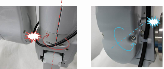
The cable may rub against the Manipulator as shown in the photos below depending on the Manipulator motion.
When routing the cable, be extra careful in this regard, and check to make sure the cable does not touch or rub against the Manipulator.
C8, C12 series-S250L, C8 series-S250P
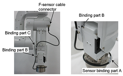
C8, C12 series Manipulator wiring example
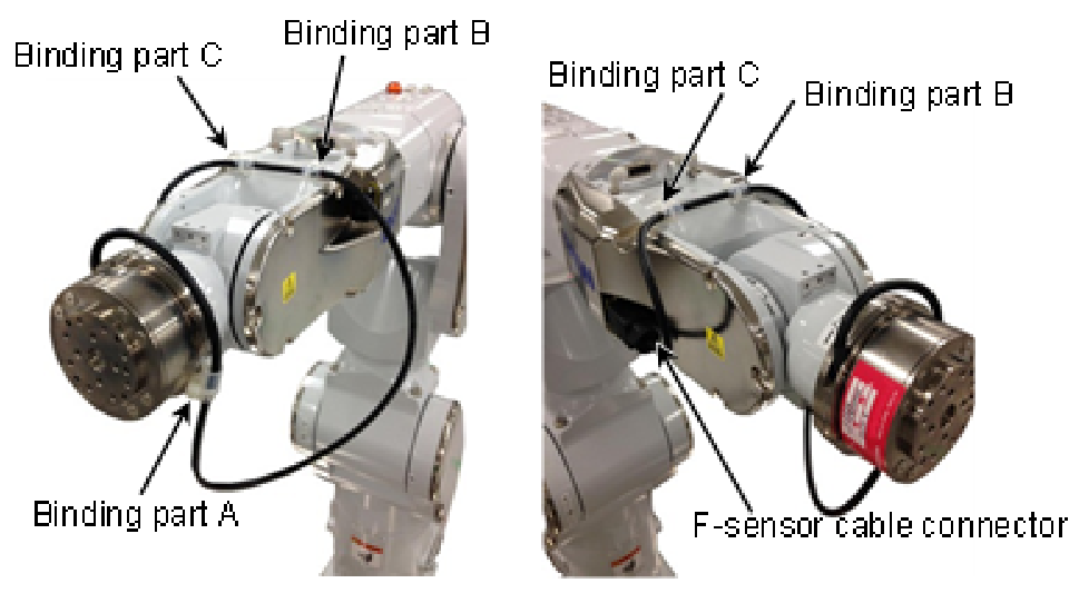
Length of A-B (excess length for rotation of J5 and J6): 475mm
C8, C12 series Manipulator rough operation range
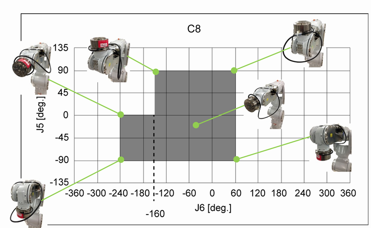
J5 | J6 |
|---|---|
| 0 to 90 deg | -160 to 60 deg |
| -90 to 0 deg | -240 to 60 deg |
CAUTION
The cables may deform during storage. Caution is required this regard. The cable's bend radius is at least five times larger than the cable diameter (R=30 mm or larger).
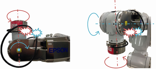
The cable may rub against the Manipulator as shown in the photos below depending on the Manipulator motion.
When routing the cable, be extra careful in this regard, and check to make sure the cable does not touch or rub against the Manipulator.
N2 series-S250H
N2 series Manipulator wiring example
Length of A-B (excess length for rotation of J5 and J6): 330 mm
When installing the cables with the above example, the cable diameter should be 13 mm or less.
Rough indication of motion range for the N2 series Manipulator when wiring with above example
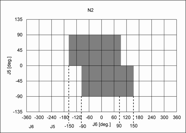
J5 | J6 |
|---|---|
| 0 to 90 deg | -150 to 90 deg |
| -90 to 0 deg | -90 to 150 deg |
CAUTION
The cables may deform during storage. Caution is required this regard. The cable's bend radius is at least five times larger than the cable diameter (R=30 mm or larger).
The cable may rub against the Manipulator as shown in the photos below depending on the Manipulator motion.
When routing the cables, make sure to check if the cables touch and rub against the Manipulator.
In particular, if the Joint #4 is rotated when the Arm #2 and #4 overlap each other, the cables may get caught between them. note that
N6 series-SH250LH
N6 series Manipulator wiring example
Length of A-B (excess length for rotation of J5 and J6): 500mm
When installing the cables with the above example, the cable diameter should be 13 mm or less.
Rough indication of motion range for the N6 series Manipulator when wiring with above example

J5 | J6 |
|---|---|
| 0 to 90 deg | -150 to 180 deg |
| -90 to 0 deg | -150 to 90 deg |
CAUTION
The cables may deform during storage. Caution is required this regard. The cable's bend radius is at least five times larger than the cable diameter (R=30 mm or larger).
The cable may rub against the Manipulator as shown in the photos below depending on the Manipulator motion.
When routing the cables, make sure to check if the cables touch and rub against the Manipulator.
In particular, if the Joint #4 is rotated when the Arm #2 and #4 overlap each other, the cables may get caught between them. note that
When passing cables through the center hole, weight of the cable may affect to the sensor value. When routing the cable, be careful for the fixing position.
If the cable weight affects to operations, refer to the wiring example in this section and fix the cable.
G series, GX series-S2503, S2506, S25010
Wiring example 1: When using the D-sub
G6, G10, G20, GX8, GX10, and GX20 series use the user connector D-sub (9-pin) to install the Force Sensor.

Wiring example 2: When using the cable duct, external wiring option, etc.
For G3, GX4 series, install the cables on the exterior of the Manipulator using the cable duct.
When installing the cables outside the Manipulator, make sure to install the ground wire of the relay cable to the specified position on the Manipulator.

For G6, G10, G20, GX8, GX10, and GX20 series, external wiring is available with the following option products.
Option product | Code | ||
|---|---|---|---|
External wiring External wiring unit | G6-***S | For Table top mounting /standard model | R12NZ900GX |
| GX8-***S | For Table top mounting /standard model | R12NZ901BY | |
| G6-***S | For Ceiling /Wall mounting /standard model | R12NZ900GY | |
| GX8-***SR/SW | For Ceiling /Wall mounting /standard model | R12NZ901BZ | |
| G10/G20-***S | For Table top mounting /standard model | R12NZ900GZ | |
| GX10/GX20-B***S | |||
| G10/G20-***SR/SW | For Ceiling /Wall mounting /standard model | R12B031912 | |
| GX10/GX20-B***SR/SW | |||
| Relay cable | R12NZ900RW | ||

Wiring example 1 and 2 use the attached cable mounts and wire ties for the following fixing parts A and B. For other parts, fix the cables according to the Manipulator motion.

CAUTION
The cables may deform during storage. Caution is required this regard. The cable's bend radius is at least five times larger than the cable diameter (R=30 mm or larger).
The cable may rub against the Manipulator or get under tension as shown in the photo below depending on the Manipulator motion.
When routing the cable, be careful in this regard and check if it touches and rubs against the Manipulator or is under tension.

RS series-S2503
RS series uses the user connector D-sub (15-pin) for installing the Force Sensor. Connect the user connector and the Force Sensor cable by using the attached branch cable. The branch cable divides the user connector D-sub (15-pin) to 6-pin and 9-pin.

Fix the fixing parts A and B using the attached wire ties and the cable mounts. For other parts, fix the cables according to the Manipulator motion.
Length of A-B (excess length for rotation of J4): 350 mm

When installing the cables with the above example, set the Manipulator motion with the following range as a rough guide.
| J4 |
|---|
| +180 deg |
| - 180 deg |
Among the user connector D-sub (15-pin), branches 6-pin with the branch cable and use it for the Force Sensor. Use the remaining 9-pin by referring to the figure below.

CAUTION
- The cables may deform during storage. Caution is required this regard. The cable's bend radius is at least five times larger than the cable diameter (R=30 mm or larger).
- The cable may rub against the Manipulator as shown in the photos below depending on the Manipulator motion. When routing the cable, be extra careful in this regard, and check to make sure the cable does not touch or rub against the Manipulator.
