Installing the Force Sensor
For S250N (C4 series)
Turn OFF the Controller.
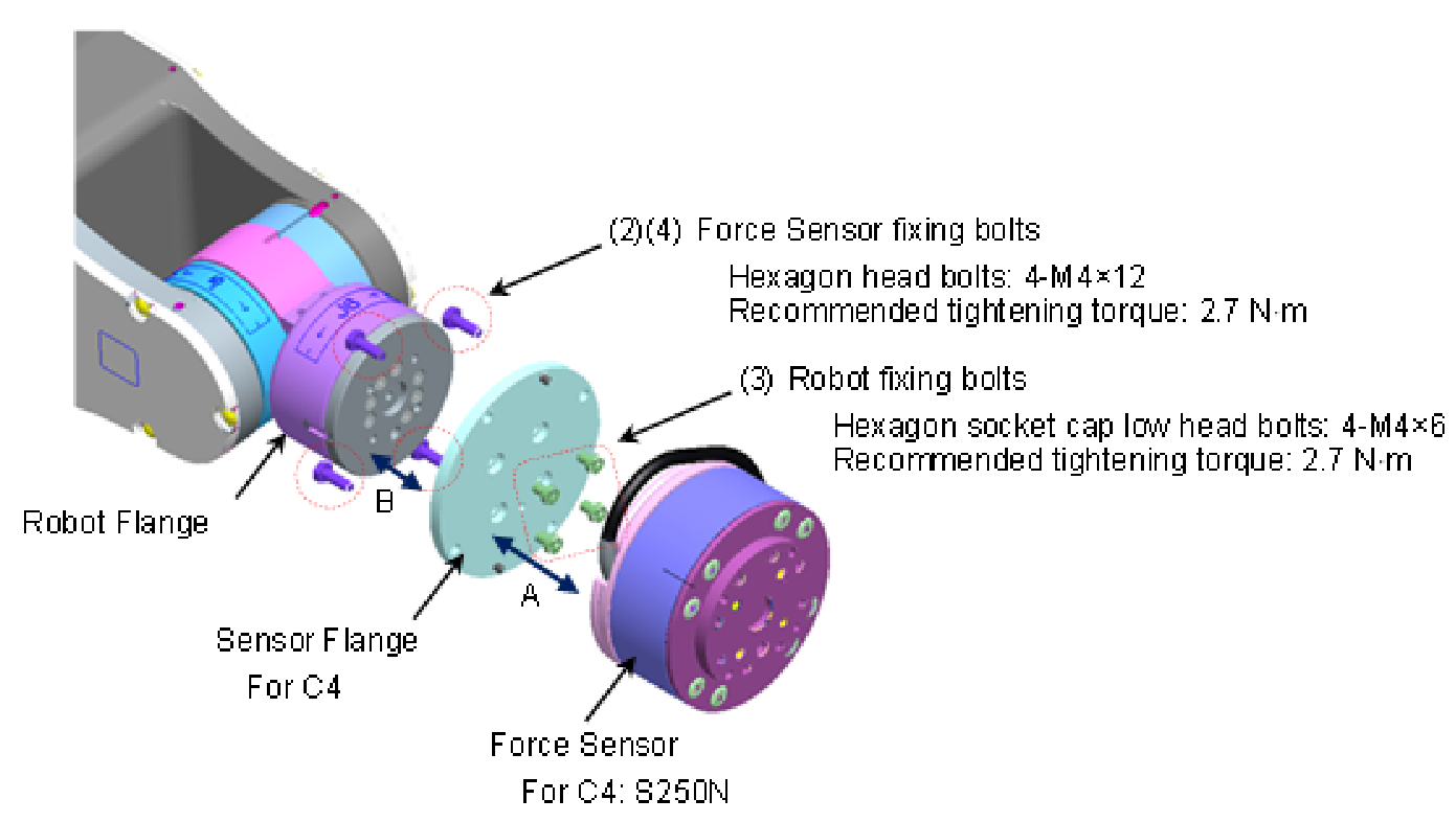
Remove the sensor flange from the Force Sensor. (A)
Force Sensor fixing bolts (Hexagon head bolts: 4-M4×12)
(The sensor is fixed to the sensor flange at the time of shipment.)Install the sensor flange on the robot flange. (B)
Align the two positioning points on the sensor flange (its positioning pins and the projection at its center) with the robot flange and fit the two together. Fix the sensor flange to the robot flange with the robot fixing bolts included with shipment.
Robot fixing bolts (Hexagon socket cap low head bolts: 4-M4×6)
Recommended tightening torque: 2.7 N mInstall the Force Sensor on the sensor flange fixed in step 3. (A)There are two types of board for the sensor. The installation method varies depending on the sensor. note that


Align the cutouts (C) on the sensor flange and the Force Sensor. Install the sensor by inserting the two positioning pins of the sensor flange to the sensor.
At this time, adjust the position of the Force Sensor cable so that the part wrapped with the heat shrinkable tube to be at (D).
Fix the sensor flange and the Force Sensor with the bolts removed in the step (2).
Force Sensor fixing bolts (Hexagon head bolts: 4-M4×12)
Recommended tightening torque: 2.7 N mFix the Force Sensor cable to the Manipulator.
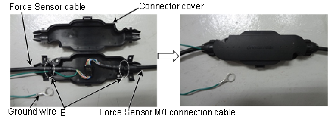
Set the cable so as not to interfere with Manipulator motion and not to apply load on the cable.Connect the Force Sensor cable and Force Sensor M/I connection cable.
Store the connecting part to the connector cover. Fix the cables with wire ties included with shipment. (E)
Close the connector cover.
Set the cable so as not to interfere with Manipulator motion and not to apply load on the cable.
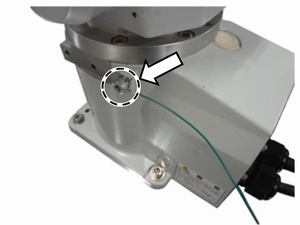
Fix the ground terminal of the Force Sensor lead to the Manipulator base.
Hexagon head bolts: M8x12
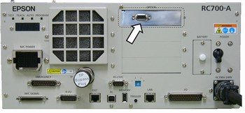
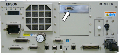
Connect the Force Sensor M/I connection cable to the Force Sensor I/F to be used.
Connect to the Connector Sensor Port for Force Sensor.
S250L (For C8, C12 series: IP20 compliant)
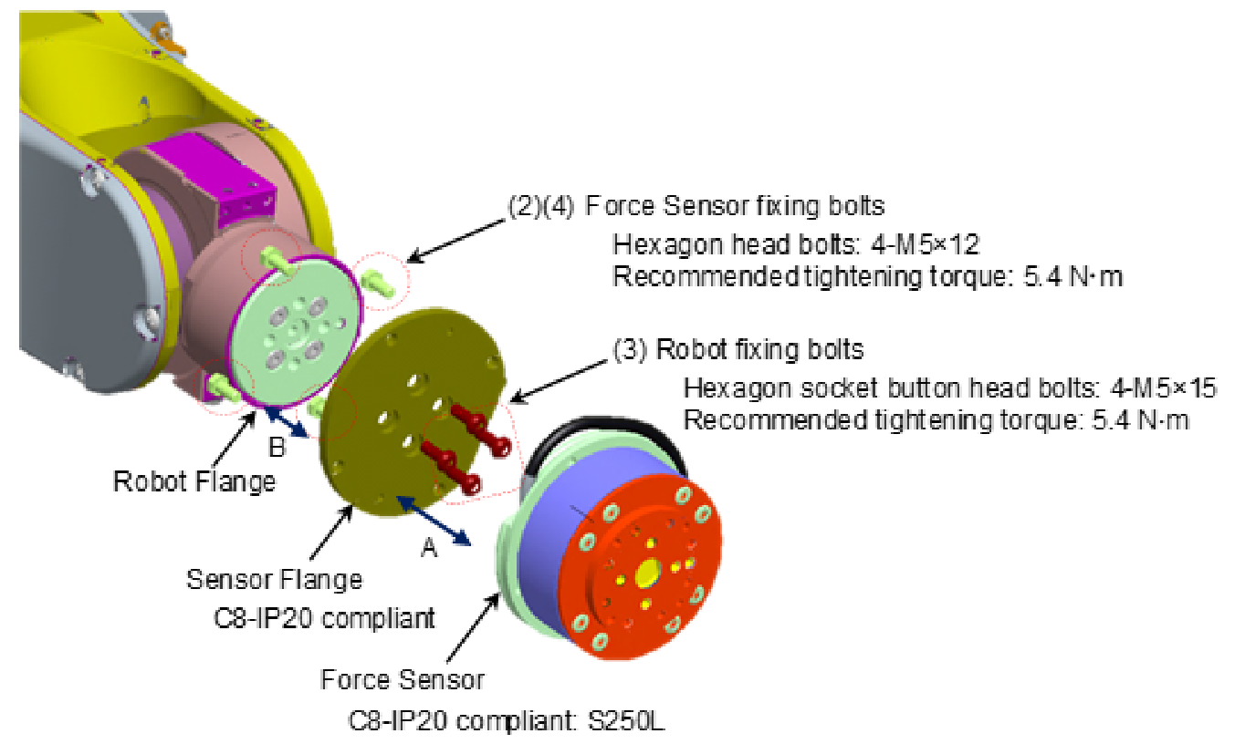
- Turn OFF the Controller.
- Remove the sensor flange from the Force Sensor. (A)
Force Sensor fixing bolts (Hexagon head bolts: 4-M5×12)
(The sensor is fixed to the sensor flange at the time of shipment.) - Install the sensor flange on the robot flange. (B)
Align the two positioning points on the sensor flange (its positioning pins and the projection at its center) with the robot flange and fit the two together. Fix the sensor flange to the robot flange with the robot fixing bolts included with shipment.
Robot fixing bolts (Hexagon socket button head bolts: 4-M5×15)
Recommended tightening torque: 5.4 N m - Install the Force Sensor on the sensor flange fixed in step 3. (A)There are two types of board for the sensor but note that the sensor installation method is the same. note that
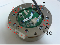
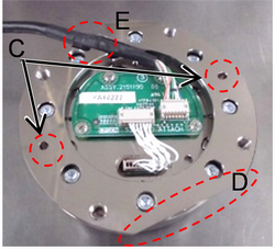
Align the cutouts (D) on the sensor flange and the Force Sensor. Insert the sensor flange by inserting the two positioning pins on the sensor flange to the positioning holes (C) on the sensor.
At this time, adjust the position of the Force Sensor cable so that the part wrapped with the heat shrinkable tube to be at (E).
Fix the sensor flange and the Force Sensor with the bolts removed in step 2.
Force Sensor fixing bolts (Hexagon head bolts: 4-M5×12)
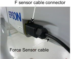
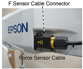
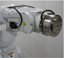
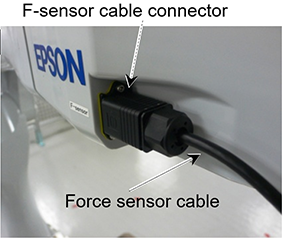
Recommended tightening torque: 5.4 N m - Connect the Force Sensor cable to the F-sensor cable connector on the Manipulator.
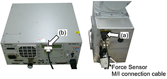
There are 2 types of Connector for Robot and Force Sensor as shown below. note that

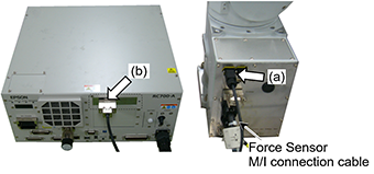
Connect the Force Sensor M/I connection cable to (a) and (b).
F-sensor cable connector
Connector Sensor Port for Force Sensor of Force Sensor I/F to be used.
Operate the Manipulator to any posture, and then record the initial sensor output data.
S250P (For C8 series: IP67 compliant)
Turn OFF the Controller.
Remove the sensor flange from the Force Sensor. (A)
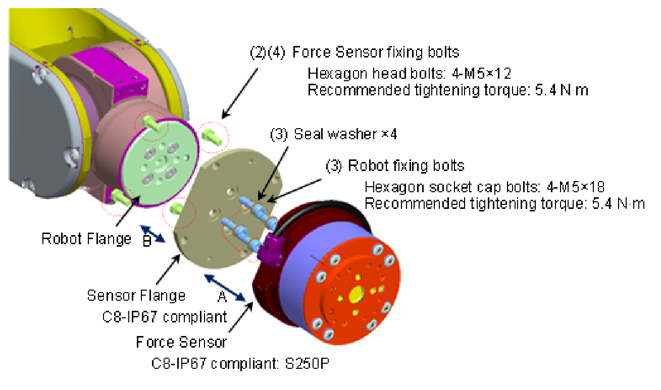
Force Sensor fixing bolts (Hexagon head bolts: 4-M5×12)(The sensor is installed to the sensor flange at the time of shipment.)Install the sensor flange on the robot flange. (B)
First, insert the sensor flange while aligning its two positioning points (positioning pins and the projection at the center) to the robot flange.
Then, insert the seal washers to the root of the robot fixing bolts included with shipment.
Robot fixing bolts (Hexagon socket cap bolts: 4-M5×18)
Recommended tightening torque: 5.4 N mInstall the Force Sensor on the sensor flange fixed in step 3. (A)
Viewed from behind, there are three types of sensor exterior, but the installation method is the same for all of them. note that
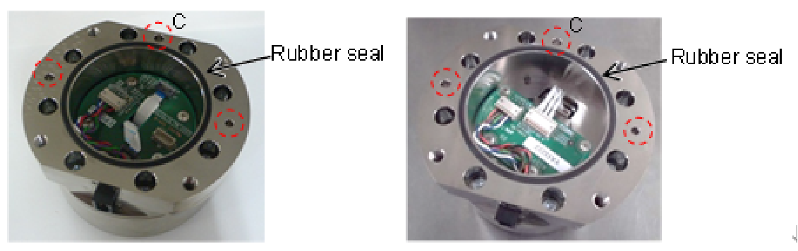
Install the Force Sensor so that the three positioning pins on the sensor flange and the positioning holes (C) on the sensor fit each other. When inserting the sensor, try to prevent the foreign material from attaching to the mounting face. Also, be careful not to touch the rubber seal. Fix the sensor flange and the Force Sensor with the bolts removed in step 2.
Force Sensor fixing bolts (Hexagon head bolts: 4-M5×12)
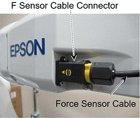
Recommended tightening torque: 5.4 N mConnect the Force Sensor cable to the F-sensor cable connector on the Manipulator.
There are 2 types of Connector for Robot and Force Sensor as shown below. note that
Connect the Force Sensor M/I connection cable to (a) and (b).
- (a) F Sensor Cable Connector
- (b) Connector Sensor Port for Force Sensor of Force Sensor I/F to be used.
How to lock the Connector with the lock:
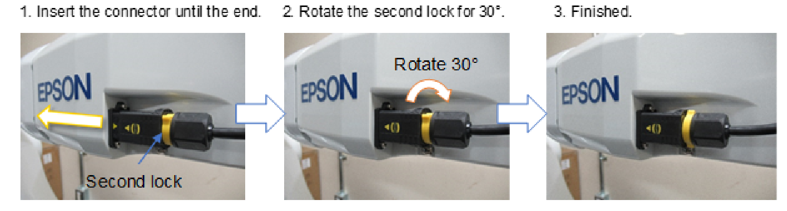
For S250H (N2 series)
Tilt Joint #6 about +20° from the origin posture.
Turn OFF the Controller.
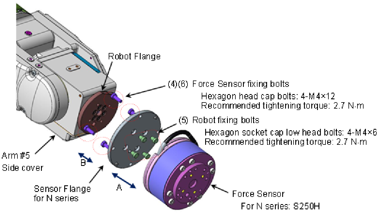
Remove the Arm #5 side cover of the Manipulator.
(Cross recessed head screws: 4-M3×6)Remove the sensor flange from the Force Sensor. (A)
Force Sensor fixing bolts (Hexagon head bolts: 4-M4×12)
(The sensor is fixed to the sensor flange at the time of shipment.)Install the sensor flange on the robot flange. (B)
First, insert the sensor flange while aligning its two positioning points (positioning pins and the projection at the center) to the robot flange.
Fix the sensor flange to the robot flange with the robot fixing bolts included with shipment.
Robot fixing bolts (Hexagon socket cap low head bolts: 4-M4×6)
Recommended tightening torque: 2.7 N mInstall the Force Sensor on the sensor flange fixed in step 5. (A)
There are two types of board for the sensor. The installation method varies depending on the sensor. note that
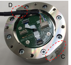
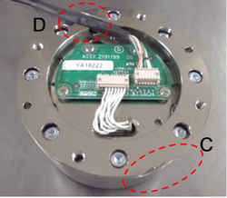
Align the cutouts (C) on the sensor flange and the Force Sensor. Install the sensor by inserting the two positioning pins of the sensor flange to the sensor.
At this time, adjust the position of the Force Sensor cable so that the part wrapped with the heat shrinkable tube to be at (D).Fix the sensor flange and the Force Sensor with the bolts removed in step 4.
Force Sensor fixing bolts (Hexagon head bolts: 4-M4×12)
Recommended tightening torque: 2.7 N mInstall the Arm #5 side cover of the Manipulator.
(Cross recessed head screws: 4-M3×6
Recommended tightening torque: 0.45 N m)Fix the Force Sensor cable to the Manipulator.
Set the cable so as not to interfere with Manipulator motion and not to apply load on the cable.Connect the Force Sensor cable to the following connector.
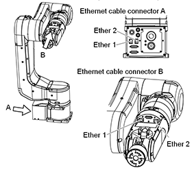
Ethernet cable connector A (Ether1, or Ether2)
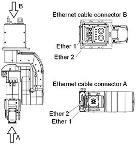
Connect the Force Sensor M/I connection cable to (a) and (b).
- (a): Ethernet cable connector B Connector with the same name as the one connected in step (9) (Ether1, or Ether2)
- (b): Connect to Force Sensor I/F to be used Connect to the Connector Sensor Port for Force Sensor.

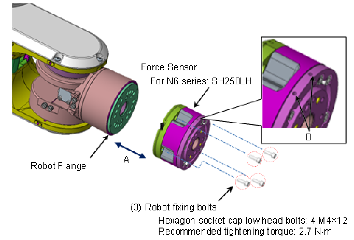
For SH250LH (N6 series)
CAUTION
If fixing the cables in B parts, Force Sensor value may be affected. For the wiring example, refer to the following section.
Wiring of the Force Sensor Cable
- Move Joint #6 of the robot to the origin posture.
- Turn OFF the Controller.
- Install the sensor flange on the robot flange. (A)
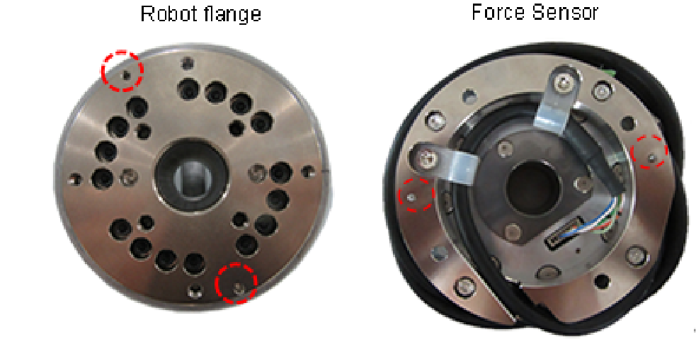
First, insert the sensor flange while aligning the two positioning points on the Force Sensor (positioning pins) to the robot flange. (See the red circles on the pictures below)
Fix the sensor flange to the robot flange with the robot fixing bolts included with shipment.
Robot fixing bolts (Hexagon socket cap low head bolts: 4-M4×12)
Recommended tightening torque: 2.7 N m
- Fix the Force Sensor cable to the Manipulator.
Set the cable so as not to interfere with Manipulator motion and not to apply load on the cable. - Connect the Force Sensor cable to the following connector.
Ethernet cable connector A (Ether1, or Ether2)
- Connect the Force Sensor M/I connection cable to (a) and (b).
- (a) : Ethernet cable connector B
Connector with the same name as the one connected in step (5) (Ether1 or Ether2) - (b): Connect to Force Sensor I/F to be used
Connect to the Connector Sensor Port for Force Sensor.
- (a) : Ethernet cable connector B
S2503, S2506, S25010 (For G, RS, GX series)

- Turn OFF the Controller.
- Remove the sensor flange from the Force Sensor. (A)
Force Sensor fixing bolts (Hexagon socket head cap bolts: 4-M4×15)
(The sensor is fixed to the sensor flange at the time of shipment.) - Fix the sensor flange and the adapter (B)
Sensor flange fixing bolts (Hexagon socket head bolts 4-M5×15)
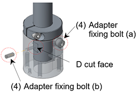
Recommended tightening torque: 8.0 N m - Insert and fix the adapter at 30 mm from the end of the Z-axis shaft. (C)
If the Z stopper position has not been changed since the time of shipment, fix the adapter where it touches the Z stopper.
Fix with the following bolts (a) and (b). Adjust the direction of the bolt (b) so as to touch the D-cut face on the Z-axis shaft vertically.
- Adapter fixing bolt (a):
Stud clamp bolt (Hexagon socket head cap bolt: M5×20)
Recommended tightening torque: 8.0 N m- Adapter fixing bolt (b):
Set screw (Hexagon socket set screw: M4×10)
Recommended tightening torque: 2.4 N m
- Connect the Force Sensor cable to the connector (D) on the Force Sensor.
There are two types of board for the sensor. The installation method varies depending on the sensor. note that
When passing the Force Sensor cable to the Z-axis hollow shaft, follow the following steps.
(1) Run the Force Sensor cable through the shaft from its upper part.
(2) Pull the cable out through the opening in the adapter.
(3) Connect the Force Sensor cable to the connector (D) on the Force Sensor.
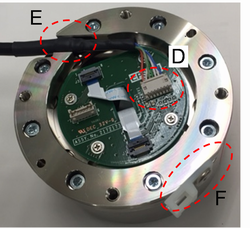
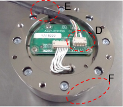
- Install the Force Sensor on the sensor flange fixed in step 3.
(A)Align the cutouts (F) on the sensor flange and the Force Sensor. Insert the sensor flange while inserting the two positioning pins on the sensor flange to the sensor. At this time, adjust the position of the Force Sensor cable so that the part wrapped with the heat shrinkable tube to be at (E). - Fix the sensor flange and the Force Sensor with the bolts removed in step 2.
Force Sensor fixing bolts (Hexagon socket head cap bolts: 4-M4×15)
Recommended tightening torque: 4.0 N m - Fix the Force Sensor cable to the Manipulator.
Set the cable so as not to interfere with Manipulator motion and not to apply load on the cable. For details of cable wiring and grounding, refer to the following section. Hardware Wiring of the Force Sensor Cable - Connect the Force Sensor M/I connection cable to (a) and (b).
- (a) : F Sensor Cable Connector
- (b): Connect to Force Sensor I/F to be used Connect to the Connector Sensor Port for Force Sensor.

CAUTION
In the case of RS series, when connecting by aligning the Force Sensor with D cut face, the positive and negative of the X axis and Y axis will be inverted 180 degrees. Sensor labels will be inverted as well.
Please take the following actions since force control of X axis and Y axis will be worked in reverse. (When using the flange supplied by us.)
When using the firmware that is Ver.7.5.5.x or before:
Execute the following SPEL+ command.
> Fset Robot.FlangOffset, 0, 0, -22, 0, 0, 180Ref: Epson RC+ 8.0 Option Force Guide 8.0 SPEL+ Language Reference: FlangeOffset property
When updating the firmware from Ver.7.5.5.x or before to Ver.7.5.6.0 or later:
Click the [Defaults] button in Epson RC+ Menu - [System Configuration] - [Controller] - [Force Sensor] Panel.
Ref: Epson RC+ 8.0 Option Force Guide 8.0 Software [Robot Manager] (Tools Menu)