[Robot Manager] (Tools Menu)
![]() : F6
: F6
[Tools]-[Robot Manager]-[Force] Panel
Force: You can enter and delete the force control, force trigger, force coordinate system, force monitor, and force motion restriction objects.
When you select a force file, the Controller loads it into the memory. When using Robot Manager as an MDI sub-window, enter "Ctrl+S" to save the force data.
[Control] Panel
You can edit the force control object.

Item | Description |
|---|---|
| Force File | Selects the force file. |
| Show defined only | Display the defined data only. |
| Label | Sets the label (Label property). |
| Description | Sets the description (Description property). |
| Properties | Selects the properties to set the value. |
| [Drop-down list] | Displays a list of values that can be selected. Select a value. |
| [Impedance Wizard] | Displays Impedance Wizard, in which you can set each of the property values for force control objects (TargetForce, Spring, Damper, and Mass). |
| Delete Fxxx | Deletes the force object. A confirmation screen appears. |
| Delete All | Deletes all the force objects in the selected tab. A confirmation screen appears. |
| Save | Saves the values. |
| Restore | Restores the original values. A confirmation screen appears. |
Impedance Wizard
Click the [Impedance Wizard] button
 button in Properties. The [Impedance Wizard] window appears.
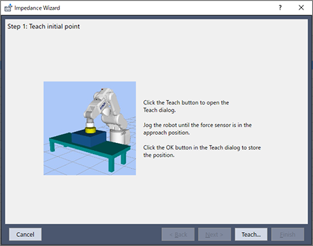
Click the [Teach…] button.
The [Teach Approach Point] dialog box appears. Move the robot to the point where the workpiece is about 1 mm above the object to be pressed.
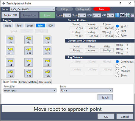
Click the [OK] button.
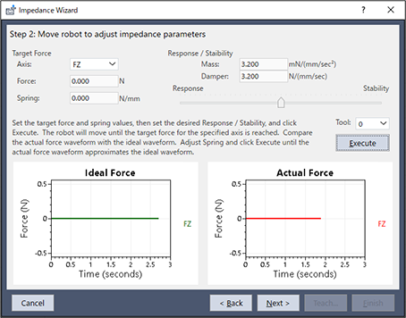
Save the current position and return to the [Impedance Wizard] window.Set the values in [Force] and [Spring] of [Target Force].
Set the values in [Mass] and [Damper] of [Response / Stability] with a slider.Set the slider to the "Stability" side first and adjust the values while checking the waveform of the actual force.
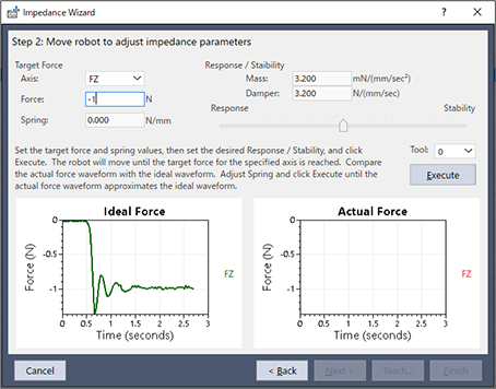
Click the [Execute] button. A confirmation dialog box is displayed.
Check that the workpiece in its initial position is within 1 mm of the object to be pressed, and then click [Yes].
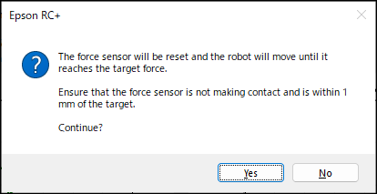
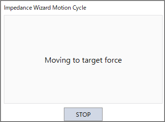
The robot moves until the set axis reaches the target force. To stop the robot during movement, click the [STOP] button.
Adjust the [Spring] value and the slider until the measured data of force approximates the ideal waveform, and then click the [Execute] button.
Repeat the procedure until the actual force waveform approximates the ideal waveform.If the waveform is vibrating or cannot settle at the target force, move the slider to "Stability" side.
If the waveform is too smooth, move the slider to "Response" side. When you move the slider too much, the force applied may change significantly. Move the slider gradually.
Note that if the [Spring] value is too large or the slider position is too stable, the robot may not be able to contact the workpiece. note that
Click the [Next] button.
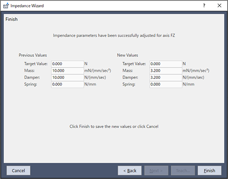
The impedance parameters before and after the adjustment for the set axis are displayed.
To save a new value, click the [Finish] button. To cancel, click the [Cancel] button.
[Trigger] Panel
You can edit the force trigger object.

[Coordinate System] Panel
You can edit the force coordinate system object.

[Monitor] Panel
You can edit the force monitor object.

[Motion Restriction] Panel
You can edit the force motion restriction object.

[Tools]- [Robot Manager]-[Mass/Gravity] Panel
You can set the values of the mass properties.

Item | Description |
|---|---|
| Mass / Gravity Wizard | Displays Mass / Gravity Wizard, in which you can set the property values of the mass property object. |
| Gravity Direction | Set the gravity direction of the robot (robot object GravityDirection property). |
| Manually define mass properties | Set the following items of the mass property object with MP (number). Label (Label property). Mass Property X / Y / Z (GravityCenter property) Description (Description Property) |
| Defaults | Sets the default value in the gravity direction. |
| Clear | Deletes the selected mass property object. |
Mass/Gravity Wizard
Click the [Mass / Gravity Wizard] button.
[Step 1: Select Mass Properties Number] appears in the [Mass / Gravity Wizard] window.
You can define the mass properties.
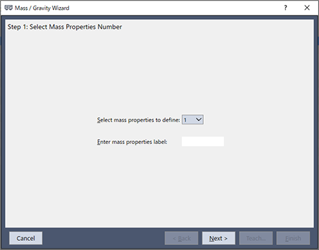
Select the number in [Select mass properties to define]. The mass properties label for the selected number is displayed in [Enter mass properties label]. The label name can be changed.
Click the [Next] button. [Step 2: Teach initial point] appears in the [Mass / Gravity Wizard] window.
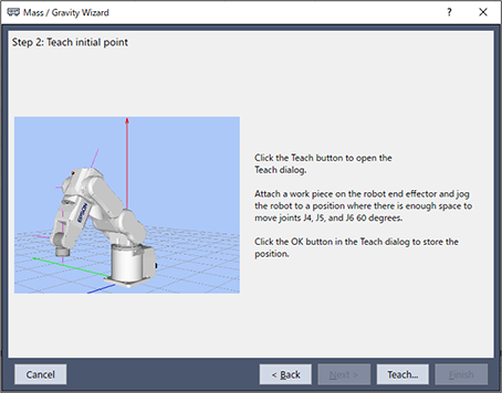
Click the [Teach] button.
The [Jog & Teach] window appears. Mount the workpiece to the end effector (hand tip) of the robot and move the robot to the position where J4, J5, and J6 can move at 60 degrees.
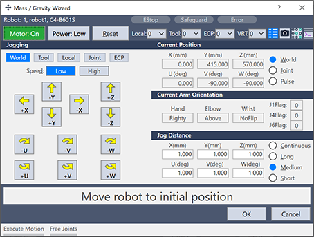
Click the [OK] button.
The position information is saved.
[Step 3: Move robot to collect data] appears in the [Mass / Gravity Wizard] window. In this step, the robot moves in 8 steps.
You can select the motion direction of joints [J4], [J5], and [J6] from "+" and "-" in [Joint Motion Directions].
You can select the speed for the posture check using step buttons from "Low" and "High" in [Motion speed].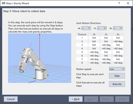
Click the [Step] button in (5) to view the posture of each step. The following message is displayed.

Click the [Yes] button to display the [Execute Command] dialog box and start moving the robot.
Click the [Step] button to check if the robot interferes with the end effector and peripherals for the posture of each step.
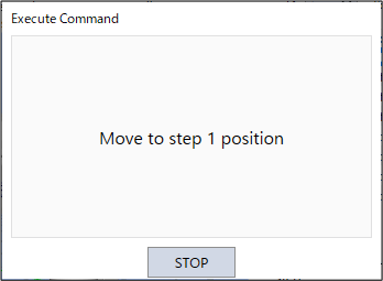
To stop the robot during movement, click the [STOP] button.Click the [Execute] button in (5) to execute all the steps to measure the mass properties.
The following message is displayed.
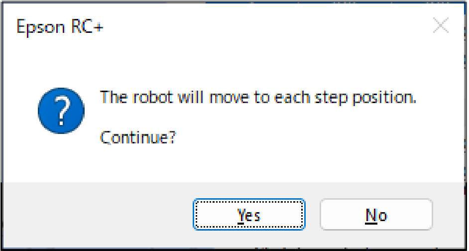
Click the [Yes] button to display the [Mass / Gravity Calibration] dialog box and start moving the robot.
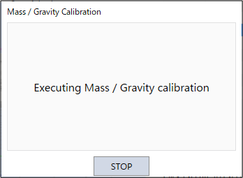
To stop the robot during movement, click the [STOP] button.When the movement is completed, the [Finish] button appears in the [Mass / Gravity Wizard] window.
The mass properties and gravity direction values are displayed in [Previous Values] and [New Values].
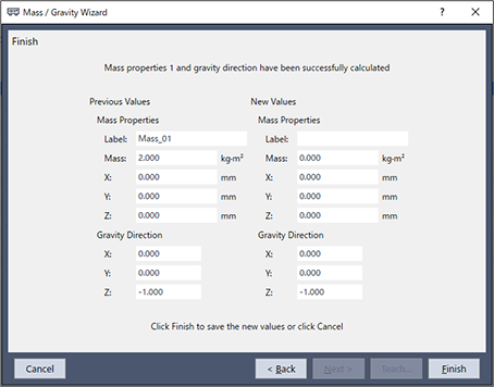
Click either of the following buttons.
[Finish] button : Saves the new values.
[Cancel] button : Cancel the new values.