Hardware Connection Configuration
This section describes the hardware connection configuration of the PLC and controller.
Hardware connection example 1
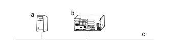
| Symbol | Description |
|---|---|
| a | PLC |
| b | Controller |
| c | Fieldbus |
Configure the hardware connection of the PLC and controller as shown in the connection example above.
- Connect the PLC and, if necessary, an HMI (Human Machine Interface) to the fieldbus.
For details on how to connect the PLC and HMI to the fieldbus, refer to the manual of each device. - Connect the controller to the fieldbus. Attach the fieldbus module to the controller and insert the cable into the fieldbus module.
Hardware connection example 2
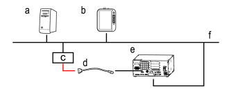
| Symbol | Description |
|---|---|
| a | PLC |
| b | HMI |
| c | Safety function module |
| d | D-Sub/TP connector conversion cable |
| e | Controller |
| f | Fieldbus |
When inputting the emergency stop signal and enable switch status sent from an HMI or similar device via a safety fieldbus to the controller, configure the system as shown in the connection example above.
- Connect a safety function module (a device that interprets the safety fieldbus communication and converts it to a signal) to the fieldbus.
- Connect the system so that the control results generated by the signals output from the safety function module are input to the controller's TP connector via a D-Sub/TP connector conversion cable.
NOTE
Prepare the cable that connects the safety function module to the D-Sub 25-pin side of the conversion cable separately (the portion indicated by the red line in "Hardware connection example 2").
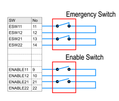
The pin arrangement of the D-Sub 25-pin connector of the D-Sub/TP conversion cable required to create a device that inputs the emergency stop and Enable switch status signals output from the safety function module to the controller is shown below.