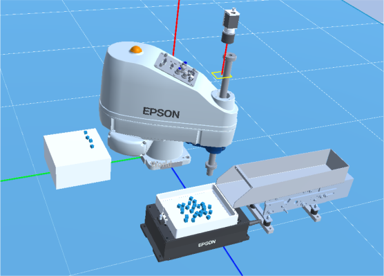
Virtual Part Feeding Function
In Epson RC+ Standard Edition or higher, you can check part feeding operation in the Simulator. This section describes the procedure for building a simple system using the virtual part feeding function.
Procedure overview
- Create a virtual controller and configure a robot
- Create a project
- Add and configure a part feeder in system configuration
- Add and configure an object corresponding to the table where parts will be placed
- Add and configure a virtual camera
- Perform vision calibration
- Create a vision sequence
- Configure parts and the feeder
- Calibrate the feeder
- Create and run a program
Procedure details
Preparation
Create a new virtual controller connection.
In system configuration, set Robot 1 to "GX8-C652S" (name: robot1).Create a new project named "PF_Sample".
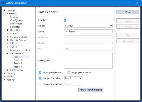
In the Epson RC+ 8.0 menu - [Setup] - [System Configuration], add a feeder (IF-A1520) under [Controller] - [Part Feeder], and configure the following settings.
- Enable [Hopper 1 Installed].
- Position setting (Position X, Y, Z): -100, 450, 0
- Collision detection setting (Collision Check): false
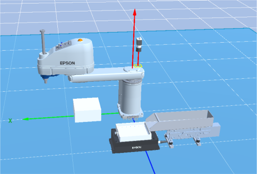
Add a table (Box object) where parts will be placed, and configure it as follows.
- Object name (Name): Table
- Size setting (Half size X, Y, Z): 100, 100, 50
- Position setting (Position X, Y, Z): 350, 0, 50
Add camera settings.
In [Vision] under the Epson RC+ 8.0 menu - [Setup] - [System Configuration], add a virtual camera.
Select [Virtual], select "acA640-120gm" as the model, and then click the [Apply] button.
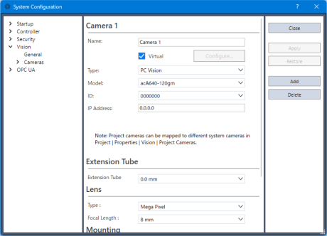
Configure the camera object as follows and place it above the feeder object.
- Position setting (Position X, Y, Z): 65, 440, 770
- Orientation setting (Rotation X, Y, Z): 180, 0, 90
Perform vision calibration.
Create and perform a calibration named "Calib".
After vision calibration is complete, move the CAD data used for calibration to a location where it will not interfere with the work.For details on camera calibration, refer to the following video manual.
Procedure for Using the Vision Simulator (opens new window)
Alternatively, refer to the following manual:
"Vision Calibration" in "Vision Guide 8.0 Software"
Sample CAD data for vision calibration is available in the following folder.
C:\EpsonRC80\Simulator\CAD\CalibBoardPerform calibration using this CAD data.
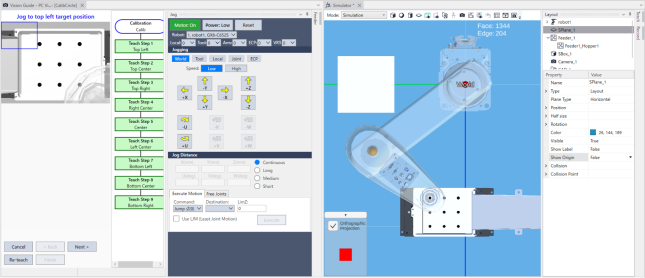
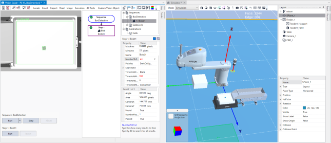
Create a vision sequence and follow the steps below to check whether the parts are detected correctly.
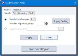
In the Feeder Operation Panel, supply one object serving as a part onto the feeder object.
- Click the [Supply Setting] button on the Feeder Operation Panel.
- Select the base object for the part from the objects currently placed in 3D.
- Select the default "Default Box" here.
Create a sequence named "BoxDetection" to recognize this part.
- Use a Blob object as the vision object for recognition.
- If the part is not recognized correctly, set the "ThresholdHigh" property to "180" and adjust it.
- Change the "NumberToFind" property from "1" to "All" to recognize all parts on the feeder.
Run the "BoxDetection" sequence and confirm that the parts are recognized correctly.
Set the "Calibration" property to the calibration "Calib" created in the earlier step.
After confirming that the parts are recognized, clear the parts from the feeder.
Click the [Clear] button on the Feeder Operation Panel.
Configure the parts and feeder using the steps below.
Open the Epson RC+ 8.0 menu - [Tools] - [Part Feeding], and add a part.
When a part is added for the first time, PartFeeding.prg is generated automatically.
Vision sequence settings are required. Configure them as follows.
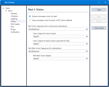
In the part supply settings, select "1" as the hopper.
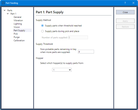
Configure the other settings as needed.
For details on the settings, refer to the following manual:
"Part Feeding 8.0 Introduction & Software - Software - Part Feeding GUI - Part Feeding Dialog Box"
Leave the default settings unchanged here.
Calibrate the feeder using the steps below.
On the part settings screen, click [Calibrate & Test] under [Calibration].
First, measure the part area.
- Click the [Part Supply] button to open the Feeder Operation Panel, and supply only one part.
- Click the [Execute] button to calculate the part area.
- Configure and adjust the feeder parameters as needed.
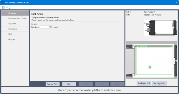
For details on the settings, refer to the following.
"Part Feeding 8.0 Introduction & Software - Software - Part Feeding GUI - Calibrate & Test"
Create a program
When the first part setting is added, the program files PartFeeding.prg and PartFeeding.inc are created automatically. A template has been added for a callback function that is automatically called from the part feeding operation process when specified conditions are met.
For details on callback functions, refer to the following.
"Part Feeding 8.0 Introduction & Software - Software - Introduction - Part Feeding Software Configuration - Callback Functions"
Here, add the processing required to operate the robot.
This program specifies the number of parts the robot picks and places when program operation starts.Create the following program as Main.prg.
Global Integer gMaxCount  ' Number of parts to pick and place
Global Integer gCount     ' Current number of picked parts

Function main
   String input$
   InputBox "Please input number of parts to pick and place", "Number of parts", "10", input$
   gMaxCount = Val(input$)

   SimSet Feeder_1.ClearSupply

   Motor On
   Power High
   Accel 100, 100
   Speed 100
   Jump XY(240, 100, -50, 0)

   PF_Start 1

   Xqt StartRobot
Fend

Function StartRobot
   TmReset 0
   Do
      If gCount >= gMaxCount Then
         Exit Do
      EndIf
   Loop

   Print "Total: ", Tmr(0), "[s]"

   PF_Stop 1
Fend
Add the following to the beginning of PartFeeding.prg.
Global Integer gMaxCount
Global Integer gCount
Additionally, rewrite the function "PF_Robot" as follows.
Function PF_Robot(PartID As Integer) As Integer
   'Robot number is set by [Tool] - [PartFeeding] - [General].
   'Set Tool, Arm, ECP if needed.

   If gCount >= gMaxCount Then
      PF_Robot = PF_CALLBACK_SUCCESS
      Exit Function
   EndIf

   String name$
   Do While PF_QueLen(PartID) > 0
      'Get position of part to be picked in the calibration robot local
      P0 = PF_QueGet(PartID)

      'Pick (Jump P0 etc)
      Go Here :Z(-50)
      Jump P0 /R :Z(-160) :U(0) LimZ -50
      SimGet robot1.NearestObjToTool(0), name$
      SimSet robot1.Pick, name$

      'Place  (Jump P1 etc)
      Jump XY(300 + (gCount / 6) * 30, -70 + (gCount Mod 6) * 30, -160, 0) LimZ -50
      SimSet robot1.Place, name$
      SimSet name$.SetParent, Table

      'Deque
      PF_QueRemove PartID

      'Check Cycle stop
      gCount = gCount + 1
      If PF_IsStopRequested(PartID) = True Or gCount >= gMaxCount Then
         Exit Do
      EndIf
   Loop

   PF_Robot = PF_CALLBACK_SUCCESS

Fend
Also, rewrite the function "PF_Control" as follows.
Function PF_Control(PartID As Integer, Control As Integer) As Integer
   String msg$
   Select Control

      Case PF_CONTROL_SUPPLY_FIRST ' Request for part supply (when empty)
         msg$ = PF_Name$(PartID) + CRLF + CRLF + "Supply " + Str$(PF_Info(PartID, PF_INFO_ID_FEEDER_CALIB_CORRECT_MAXNUM)) + " parts."

         'Sample for hopper control
         PF_Hopper 1, PartID, 3000
         Wait 3.0

      Case PF_CONTROL_SUPPLY ' Request for part supply (add up to optimum number)
         msg$ = PF_Name$(PartID) + CRLF + CRLF + "Supply additional parts."

         'Sample for hopper control
         PF_Hopper 1, PartID, 3000
         '(For parallel supplying, Wait is not needed here.)

      Case PF_CONTROL_LIGHT_ON ' Request for Front Light On
         msg$ = PF_Name$(PartID) + CRLF + CRLF + "Turn front light On."

      Case PF_CONTROL_LIGHT_OFF ' Request for Front Light Off
         msg$ = PF_Name$(PartID) + CRLF + CRLF + "Turn front light Off."

   Send

   If False And CtrlDev = 21 Then
      MsgBox msg$, MB_ICONINFORMATION
   Else
      Print msg$
   EndIf

   PF_Control = PF_CALLBACK_SUCCESS

Fend
Run the program
Click the [Run Window] button on the toolbar to display the Run window.
Select the function "main", and then click the [Start] button.
A dialog box for entering the number of parts to Pick & Place appears.
Enter any number, and then click the [OK] button.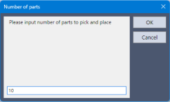
After the parts are supplied to the feeder, confirm that the robot picks them up and moves them to the table.