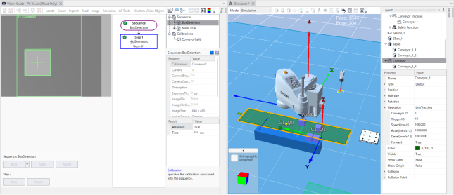
Conveyor Tracking Operation (Vision Tracking)
Next, let's create a conveyor tracking operation using vision.
The robot uses Pick & Place to move a workpiece (part) detected by vision from the conveyor to the table.
Procedure overview
- Create a virtual controller and configure a robot
- Create a project
- Add an object corresponding to the workpiece (part)
- Add and configure an object corresponding to the table
- Add and configure a conveyor object
- Configure and verify the supply settings for the conveyor object
- Add and configure a virtual camera
- Add conveyor tracking settings
- Perform vision calibration
- Create a vision sequence
- Perform and configure conveyor calibration
- Check workpiece (part) detection
- Create and run a program
Procedure details
Preparation
Create a new virtual controller connection.
In system configuration, set Robot 1 to "GX8-C652S" (name: robot1).Create a new project named "ConvTrack_Vision".
Add a Box object (SBox_1) corresponding to the workpiece (part) transported by the conveyor, and configure it as follows.
- Change it to any color.
- Position setting (Position X, Y, Z): 550, 550, 25 (Move it to a location where it will not interfere with the work.)
Add a table (Box object) where the workpiece (part) will be placed, and configure it as follows.
- Object name (Name): Table
- Size setting (Half size X, Y, Z): 40, 300, 50
- Position setting (Position X, Y, Z): -550, 0, 50
Add a conveyor object and configure it as follows.
- Position setting (Position X, Y, Z): -400, 0, 100
- Orientation setting (Rotation Z): 90
- Size setting (Half size Height, Width): 500, 100
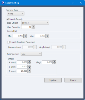
Configure the supply settings for the workpiece (part).
- Click the "Operation" - "Supply" property of the conveyor object added in the previous step.
- In the displayed Supply Setting dialog box, select [Enable Supply].
- Set [Base Object] to "SBox_1", which was added in the previous step.
- Set both [Min] and [Max] under [Interval] to "3.000".
- Set [Z] under [Offset] to "26.000".
Add camera settings.
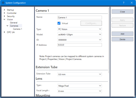
In [Vision] under the Epson RC+ 8.0 menu - [Setup] - [System Configuration], add a virtual camera.
Select [Virtual], select "acA640-120gm" as the model, and then click the [Apply] button.
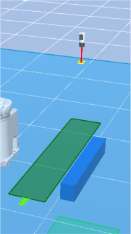
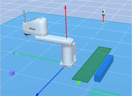
Configure the camera object as follows and place it above the conveyor object.
- Position setting (Position X, Y, Z): -400, -400, 700
- Orientation setting (Rotation X): 180
Add a conveyor tracking configuration and configure it as follows.
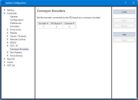
In the Epson RC+ 8.0 menu - [Setup] - [System Configuration], confirm that an encoder has been added under [Controller] - [Conveyor Encoder].
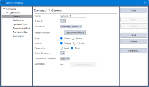
In the Epson RC+ 8.0 menu - [Tools] - [Conveyor Tracking], add a conveyor tracking configuration.
Select [Vision] for [Type].
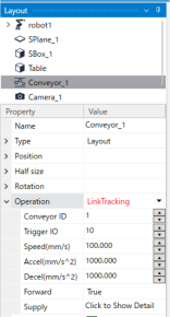
Configure the conveyor object as follows.
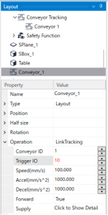
- Set the "Operation" property to "LinkTracking".
- Set the "Conveyor ID" property to "1".
Perform vision calibration.
Create and perform a calibration named "ConveyorCalib".
After vision calibration is complete, move the CAD data used for calibration to a location where it will not interfere with the work.For details on camera calibration, refer to the following manual.
"Epson RC+ Option Vision Guide Software - Vision Calibration - Calibration Procedures - Calibration Procedure: Standalone Camera"
Create a vision sequence and follow the steps below to check whether the workpiece (part) is detected correctly.
Using the Conveyor Operation Panel, move the conveyor object to transport one Box that serves as the workpiece.
Stop the conveyor object at a position within the camera field of view.
Create a sequence named "BoxDetection" to recognize this workpiece.
Run the "BoxDetection" sequence and confirm that the workpiece (part) is recognized correctly.
Set the "Calibration" property to the calibration "ConveyorCalib" created in the earlier step.
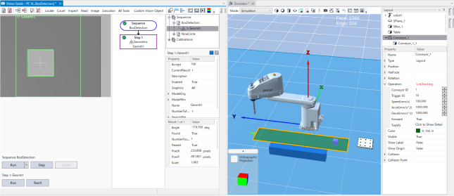
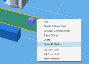
After confirming that the workpiece (part) is detected correctly, delete the workpiece (part) from the conveyor for now.
Right-click the conveyor object and select [Delete All Children].
Perform conveyor calibration.
For details on conveyor calibration in the Simulator, refer to the following.Robot Object - "Conveyor calibration"
Perform simple calibration by following the steps below.
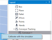
In the layout tree, expand the "Conveyor Tracking" node under the robot node.
Right-click "Conveyor 1", and then click [Calibrate with the simulator].
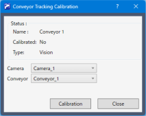
Set the "Visible" property for each of the "Conveyor Origin", "Upstream Limit", and "Downstream Limit" properties to "True".
Confirm the display of the conveyor origin, upstream limit, and downstream limit.
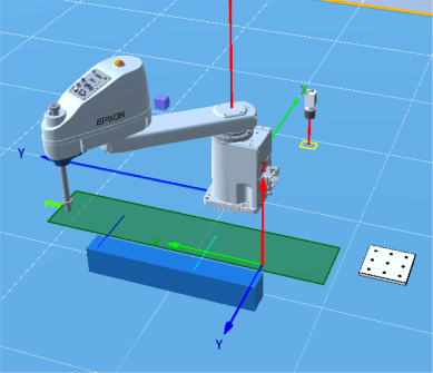
Configure double registration prevention.
Open the Epson RC+ 8.0 menu - [Tools] - [Conveyor Tracking], and set the distance for preventing double registration of workpieces to "200mm".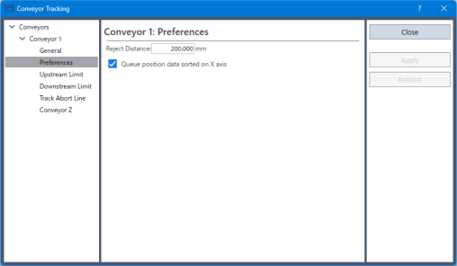
Create a program
Software trigger
Create the following program as Main.prg.
This program performs conveyor tracking operation using the camera software trigger.Function main SimSet Conveyor_1.ClearSupply Motor On Power High Speed 100 Accel 100, 100 Cnv_Mode 1, 1 Cnv_Accel 1, 2000 Cnv_QueRemove 1, All Integer i String name$ Xqt VisionDetection TmReset 0 SimSet Conveyor_1.Start For i = 1 To 10 Wait Cnv_QueLen(1, CNV_QUELEN_PICKUPAREA) > 0 Wait 0.5 Jump Cnv_QueGet(1, 0) +Z(51) SimGet robot1.NearestObjToTool(0), name$ SimSet robot1.Pick, name$ Jump Here :X(-550) :Y(i * 60 - 320) SimSet robot1.Place, name$, Table Cnv_QueRemove 1, 0 Next SimSet Conveyor_1.Stop Quit VisionDetection Print "Finished, ", Tmr(0), "[s]" Fend Function VisionDetection Integer numFound, i, state Real x, y, u Boolean found Off 10 Wait 0.5 Do VRun BoxDetection Cnv_Trigger (1) VGet BoxDetection.Geom01.NumberFound, numFound Print "Num Found ", numFound For i = 1 To numFound VGet BoxDetection.Geom01.CameraXYU(i), found, x, y, u Cnv_QueAdd 1, Cnv_Point(1, x, y) Next Wait 1 Loop FendHardware trigger
Conveyor tracking using the virtual hardware trigger of the camera object is also possible.
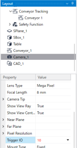
Configure the hardware trigger by following the steps below.Set the "Trigger IO" property of the camera object to "10".
Set the "Operation" - "Trigger IO" property of the conveyor object to "10", the same value set in the previous step.
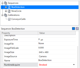
Set the "RuntimeAcquire" property of the Vision Guide sequence "BoxDetection" to "Strobed".
Modify the function "VisionDetection" in the program created above as follows.
Function VisionDetection
    Integer numFound, i, state
    Real x, y, u
    Boolean found

    Off 10
    Wait 0.5
    Do
        VRun BoxDetection
        On 10

        Do
  	      VGet BoxDetection.AcquireState, state
        Loop Until state = 3

        VGet BoxDetection.Geom01.NumberFound, numFound
        Print "Num Found ", numFound

        For i = 1 To numFound
  	      VGet BoxDetection.Geom01.CameraXYU(i), found, x, y, u
  	      Cnv_QueAdd 1, Cnv_Point(1, x, y)
        Next

        Off 10
        Wait 0.5
    Loop
Fend
Run the program
Click the [Run Window] button on the toolbar to display the Run window.
Select the function "main", and then click the [Start] button.