Conveyor Tracking Operation (Sensor Tracking)
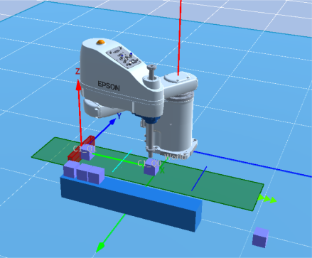
Next, let's create a conveyor tracking operation using a sensor.
The robot uses Pick & Place to move a workpiece (part) that is moving on the object and has been detected by the sensor to the table.
Procedure overview
- Create a virtual controller and configure a robot
- Create a project
- Add an object corresponding to the workpiece (part)
- Add and configure an object corresponding to the table
- Add and configure a conveyor object
- Configure and verify the supply settings for the conveyor object
- Add and configure a detection area object
The procedure up to this point is the same as described below.
The following steps are for tracking operation.
- Add conveyor tracking settings
- Perform and configure conveyor calibration
- Create and run a program
Procedure details
Preparation
The steps up to step 5 in Procedure overview are omitted because they are the same as the procedure described below.
The differences are explained below.
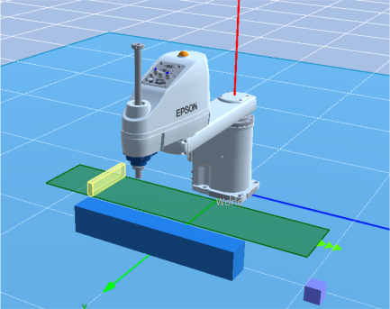
Add the detection area object "DetectionArea_1" corresponding to the sensor, and configure it as follows.
- Position setting (Position X, Y, Z): 400, -300, 125
- Orientation setting (Rotation Z): 90
Configure conveyor tracking. Set as follows.
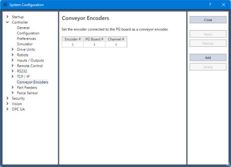
In the Epson RC+ 8.0 menu - [Setup] - [System Configuration], confirm that an encoder has been added under [Controller] - [Conveyor Encoder].
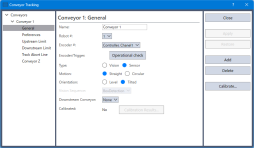
In the Epson RC+ 8.0 menu - [Tools] - [Conveyor Tracking], add a conveyor tracking configuration.
Select [Sensor] for [Type].
Configure the conveyor object as follows.
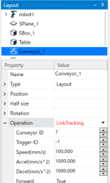
- Set the "Operation" property to "LinkTracking".
- Set the "Conveyor ID" property to "1".
Perform conveyor calibration.
For details on conveyor calibration in the Simulator, refer to the following.Robot Object - "Conveyor calibration"
Perform simple calibration by following the steps below.
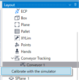
In the layout tree, expand the "Conveyor Tracking" node under the robot node.
Right-click "Conveyor 1", and then click [Calibrate with the simulator].
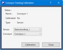
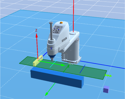
Set the "Visible" property for each of the "Conveyor Origin", "Upstream Limit", and "Downstream Limit" properties to "True".
Confirm the display of the conveyor origin, upstream limit, and downstream limit.
Configure double registration prevention.
Open the Epson RC+ 8.0 menu - [Tools] - [Conveyor Tracking], and set the distance for preventing double registration of workpieces to "200mm".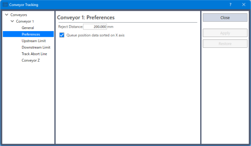
Configure the trigger settings.
Configure the following for the detection area object.
- Sensor setting (Sensor - IO Type): Output
- Sensor setting (Sensor - IO Number): 10
- Sensor setting (Sendor - Duration): 0.30
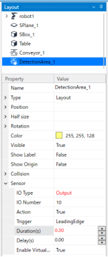
Configure the following for the conveyor object.
- Trigger IO setting (Operation - Trigger IO): 10
Set it to "10", the same value set for IO Number of the detection area object.
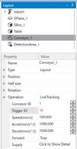
- Trigger IO setting (Operation - Trigger IO): 10
Create a program
Create the following program as Main.prg.
Function main
    SimSet Conveyor_1.ClearSupply

    Motor On
    Power High
    Speed 100
    Accel 100, 100

    Cnv_Mode 1, 1
    Cnv_Accel 1, 2000
    Cnv_QueRemove 1, All

    Integer i
    String name$

    Xqt SensorDetection

    TmReset 0
    SimSet Conveyor_1.Start

    For i = 1 To 10
        Wait Cnv_QueLen(1, CNV_QUELEN_PICKUPAREA) > 0

        Jump Cnv_QueGet(1, 0) +Z(51)

        SimGet robot1.NearestObjToTool(0), name$
        SimSet robot1.Pick, name$

        Jump Here :X(550) :Y(i * 60 - 320)

        SimSet robot1.Place, name$, Table

        Cnv_QueRemove 1, 0
    Next

    SimSet Conveyor_1.Stop
    Quit SensorDetection

    Print "Finished, ", Tmr(0), "[s]"
Fend

Function SensorDetection
    Double LPulse
    Cnv_QueRemove 1, All
    LPulse = Cnv_LPulse(1)

    Do
        If LPulse <> Cnv_LPulse(1) Then
            Cnv_QueAdd 1, Cnv_Point(1, -20, 0)
            LPulse = Cnv_LPulse(1)
        EndIf
    Loop
Fend
Run the program
Click the [Run Window] button on the toolbar to display the Run window.
In the Run Window, select the function "main", and then click the [Start] button.
Unlike standalone conveyor operation, confirm that the workpiece (part) is picked and placed by the robot without stopping the conveyor.