Force Sensor I/F board (FS2)
The Force Sensor I/F board is an optional board for the Force Sensor S250 series that serves as a 24V power supply and carries out communications.
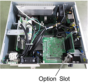
Mount the Controller on the option slot and connect the Force Sensor to communicate the Controller and the Force Sensor.
Specification
Item | Specification | |
|---|---|---|
| Outer dimensions | 206 mm × 102 mm × 24.5 mm | |
| Weight | 135 g | |
| Interface | Force Sensor communication port | D-sub 9 pin (1 port), One communications are supported |
| Operating environment | Temperature | 5 to 40° C |
| Humidity | 10 to 80% (with no condensation) | |
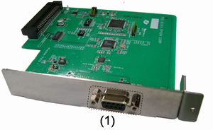
No. | Name | Function |
|---|---|---|
| 1 | Force Sensor connector | The connector to connect the Force Sensor. One sensor can be connected. |
How to Install
Warning
Only authorized personnel who have taken maintenance training held by Epson or supplier should be allowed to perform the Robot maintenance.
RC700
RC700-A
RC700-D
RC700-E
Force Sensor I/F Board Installation
- Turn OFF the Controller.
- Disconnect the power plug.
- Remove the top board. (six mounting screws)
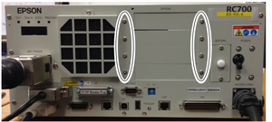
- Unscrew the option slot panel.
Remove the option panel on the side you want to mount the Force Sensor I/F board.
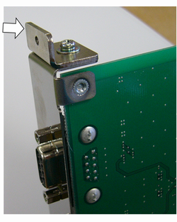
- Mount the L-shaped plate on the Force Sensor I/F board.
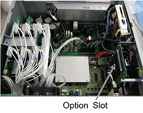
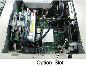
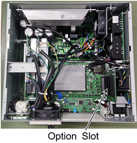
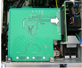
- Mount the Force Sensor I/F board as shown the picture on the right.
Push the board into option slot. (Direction of an arrow)
- Fix the attached L-shaped plate from the front side with screws.
At this time, one screw of the option slot panel will be left.
- Mount the top board. (six mounting screws)
- After connecting the power plug, turn ON the Controller and make sure that it operates properly without vibration or abnormal sounds.
Cautions about Connection
Force Sensor I/F board supplies DC24V from the connector of the Force Sensor to operate Force Sensor S250 series. Be careful about the followings.
- Do not connect any devices to the connector for the Force Sensor other than the Force Sensor. It may result in damage of connected device, Force Sensor I/F board, and the Controller.
- Do not change jumper pins or DIP switches of any kind. If you changed those, refer to the following manual and put those back. Force Sensor I/F board may not be recognized properly if changing DIP switches and jumper pins.
- "Robot Controller RC700 series Manual Functions - Force Sensor I/F Board"
- "Robot Controller RC700-D Manual Functions - Force Sensor I/F Board"
- "Robot Controller RC700-E Manual - Force Sensor I/F Board"