Sequence Wizard for a HeightInspect Sequence
Use the sequence wizard to create a HeightInspect sequence. This sequence wizard can be displayed by doing the following.
- Right click the sequence flow in the flowchart, or the sequence node in the sequence tree, and then select [Sequence Wizard].
- Click
 shown to the right of the [Click to open->] Wizard setting in the HeightInspect sequence property.
When the sequence wizard appears, configure settings as instructed on the screen.
The sequence wizard for a HeightInspect sequence can also be configured on the new sequence screen for creating a new force guide sequence. For more information, see the following section.
Software [Force Guidance] [Tools] menu
- Create a new force guide sequence - Sequence Wizard, Create a new system force guide sequence
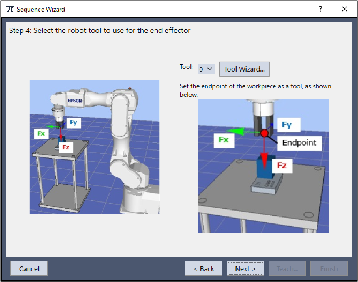
Step 1. Select the robot tool to use for the end effector
Select the tool number to be used for the HeightInspect sequence and HeightInspect object.
Item | Description, settings guide |
|---|---|
| Tool | Select the tool number to be used. Select a tool number so that the end point of the workpiece is at the tool origin point. Tool numbers set are sorted in the list. To set a new tool, use the Tool Wizard button. "Epson RC+ 8.0 User's Guide - Epson RC+ 8.0 GUI - [Tools] menu, [Tools] - [Robot Manager] - [Tool Settings] panel" Minimum value: 0 Maximum value: Maximum value for the set tool number Default: 0 |
| [Cancel] button | Cancels a new HeightInspect sequence creation. Click it to end a sequence wizard. |
| [Back] button | When opening from the new sequence creation screen, you can return to the previous Step. |
| [Next] button | Proceeds to the next Step. |
| [Finish] button | You cannot click this button. |
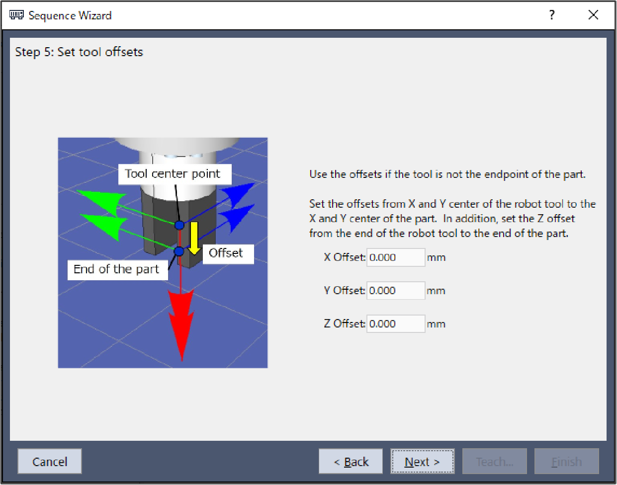
Step 2. Set tool offsets
When the tool set in Step 1 is not set in the center of the workpiece tip, this setting is required. Set the offset amount from the tool to the center of the workpiece tip.
Item | Description, setting guide |
|---|---|
| X Offset | Sets the offset amount in the X direction from the tool set in Step 1 to the tip of the workpiece. Minimum value: -2000.000 [mm] Maximum value: 2000.000 [mm] Default: 0.000[mm] |
| Y Offset | Sets the offset amount in the Y direction from the tool set in Step 1 to the tip of the workpiece. Minimum value: -2000.000 [mm] Maximum value: 2000.000 [mm] Default: 0.000[mm] |
| Z Offset | Sets the offset amount in the Z direction from the tool set in Step 1 to the tip of the workpiece. Minimum value: -2000.000 [mm] Maximum value: 2000.000 [mm] Default: 0.000[mm] |
| [Cancel] button | Cancels a new HeightInspect sequence creation. Click it to end a sequence wizard. |
| [Back] button | Returns to the previous Step. |
| [Next] button | Proceeds to the next Step. |
| [Finish] button | You cannot click this button. |
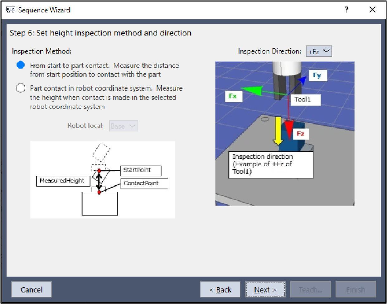
Step 3. Set height inspection method and direction
Set the height inspection method.
Select "Tool" to measure the distance from the position when starting the sequence to the contact point of workpiece.
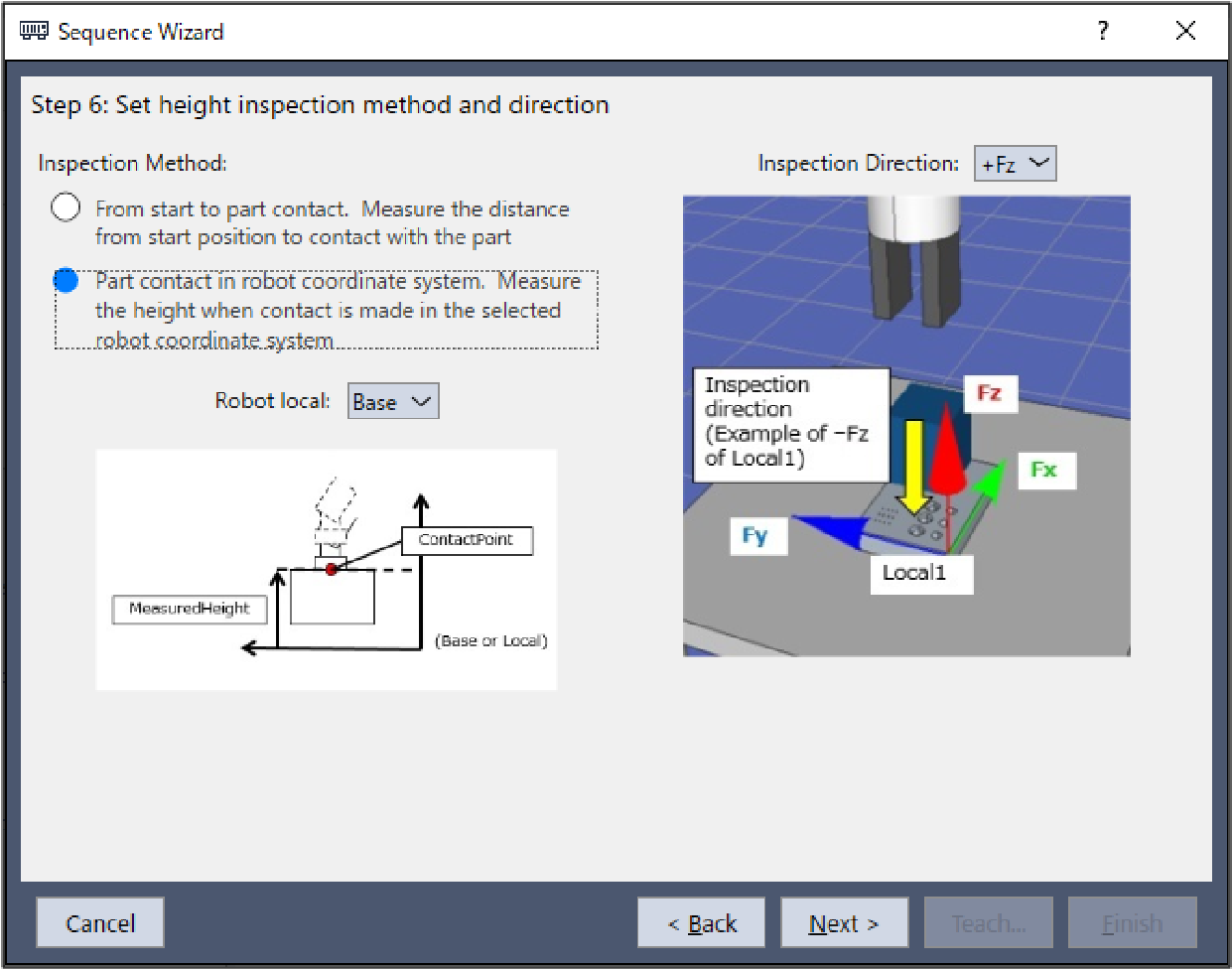
Select "Base or Local" to measure the position on the specified robot coordinate system when contacting workpiece.
Item | Description, setting guide |
|---|---|
| Robot local | Select the coordinate system used by the HeightInspect sequence. When the height inspection method is set to "Base" or "Local", the robot will move in the corresponding coordinate system. Select the coordinate system according to the orientation of the workpiece being inserted. Minimum value: Base (0) Maximum value: 15 Default: Base |
| Inspection direction | Select the direction of the inspection. When the inspection method is set to "Tool", the HeightInspect sequence and HeightInspect object will move in the direction of the inspection selected for the tool coordinate system set in Step 1. When the height inspection method is set to "Base" or "Local", the HeightInspect sequence and HeightInspect object will move in the direction of the inspection selected for the base or local coordinate system set as the coordinate system. Values: +Fx, -Fx, +Fy, -Fy, +Fz, -Fz Default: +Fz |
| [Cancel] button | Cancels a new HeightInspect sequence creation. Click it to end a sequence wizard. |
| [Back] button | Returns to the previous Step. |
| [Next] button | Proceeds to the next Step. |
| [Finish] button | You cannot click this button. |
Step 4. Configure the reference distance/position and tolerance
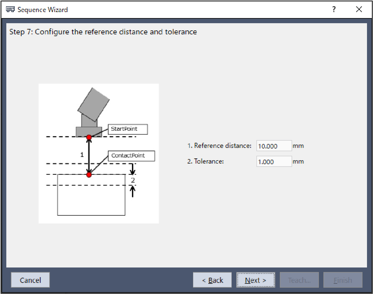
When the tool coordinate system is selected in Step 3, configure the reference distance and tolerance of the height inspection.
Item | Description, setting guide |
|---|---|
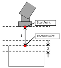
| Reference distance | Set a reference distance. This is the moving distance in the direction set in the height inspect direction of the coordinate system set in the inspection method in Step 3. The reference distance is distance 1 (in the figure below) between the operation start point indicated by the upper red dot in the figure below and the planned contact point indicated by the lower red dot. Teach the robot a start point of the motion that shortens the inspection reference distance as much as possible. As the force control function is slower than position control, longer inspection reference distances will result in longer cycle times.
Minimum value: 0 [mm] Maximum value: 50 [mm] Default: 10[mm] |
| Effective Range | Set a tolerance. The tolerance is the length of 2 in the inspection success condition range in the figure in Reference distance. The lower this tolerance value, the stricter success conditions are for the operation. It is recommended that you increase the tolerance, and then adjust it back based on actual operation results obtained. Minimum value: 0.01 [mm] Maximum value: 10 [mm] Default: 1[mm] |
| [Cancel] button | Cancels a new HeightInspect sequence creation. Click it to end a sequence wizard. |
| [Back] button | Returns to the previous Step. |
| [Next] button | Proceeds to the next Step. |
| [Finish] button | You cannot click this button. |
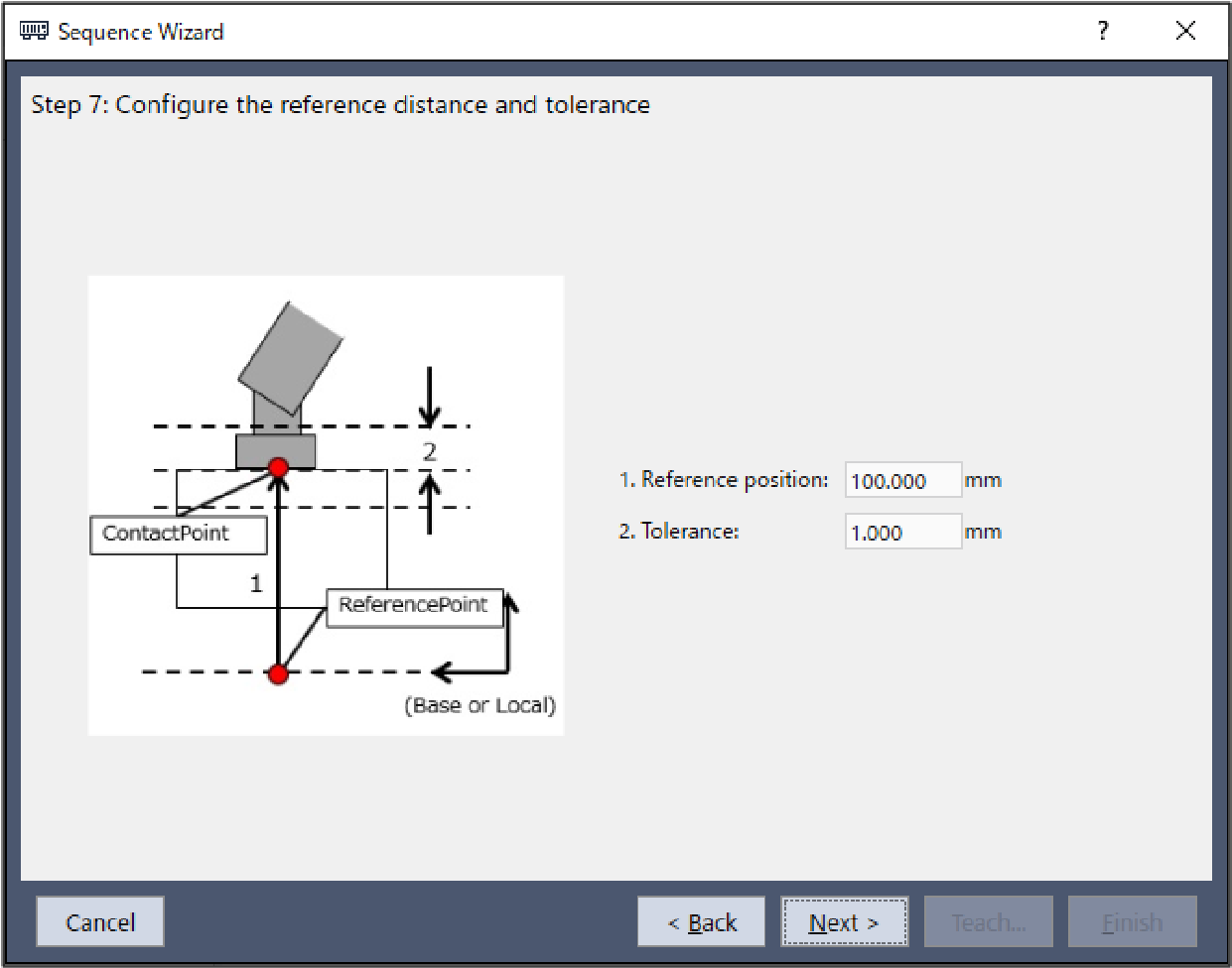
When the "Base or Local" coordinate system is selected in Step 3, set the reference position and tolerance for height inspection.
Item | Description, setting guide |
|---|---|
| Reference position | Set a reference position. This is the position in the direction set in the height inspecting direction of the coordinate system set in the inspection method in Step 3. The reference position is the position to be contacted, which is indicated by the upper red dot in the figure below. Teach the robot a start point of the motion that shortens the distance from the start point to the contact point as much as possible. As the force control function is slower than position control, longer motion distances will result in longer cycle times.
Minimum value: -2000 [mm] Maximum value: 2000 [mm] Default: 100[mm] |
| Effective Range | Set a tolerance. The tolerance is the length of 2 in the inspection success condition range in the figure in Reference position. The lower this tolerance value, the stricter success conditions are for the operation. It is recommended that you increase the tolerance, and then adjust it back based on actual operation results obtained. Minimum value: 0.01 [mm] Maximum value: 10 [mm] Default: 1[mm] |
| [Cancel] button | Cancels a new HeightInspect sequence creation. Click it to end a sequence wizard. |
| [Back] button | Returns to the previous Step. |
| [Next] button | Proceeds to the next Step. |
| [Finish] button | You cannot click this button. |

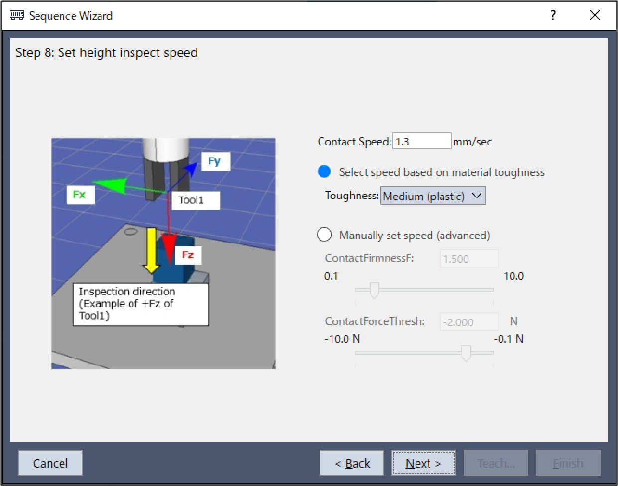
Step 5. Set height inspect speed
Set the contact speed of the height inspection from the preset. While this property setting can be configured directly, this is for advanced users.
Item | Description, setting guide |
|---|---|
| Toughness | Select the toughness of the workpiece material. Choose from three presets, "Fragile", "Normal", and "Hard". A guideline for the different levels of toughness to choose from is provided below. Fragile: Glass Normal: Plastic Hard: Metal When "Fragile" is selected for toughness, the contact speed will be slow. When "Hard" is selected, the contact speed will be increased. This can be set by selecting "Select speed based on material toughness". |
| ContactFirmnessF | Set a toughness of the force control function. When you set a large value: It becomes tough and slows down the contact speed. When you set a small value: It becomes soft and increases the contact speed, but may be vibrating. This can be set by selecting "Manually set speed (advanced)". Press the Minimum value: 0.1 [mm] Maximum value: 10 [mm] Default: 1.5[mm] |
| ContactForceThresh | Set a threshold to determine that the target is contacted. This can be set by selecting "Manually set speed (advanced)". Press the |
When the contact direction is in the positive direction: Minimum value: -10 [N] Maximum value: -0.1 [N] Default: -2 [N] | |
When the contact direction is in the negative direction: Minimum value: 0.1 [N] Maximum value: 10 [N] Default: 2 [N] | |
| [Cancel] button | Cancels a new HeightInspect sequence creation. Click it to end a sequence wizard. |
| [Back] button | Returns to the previous Step. |
| [Next] button | Proceeds to the next Step. |
| [Finish] button | You cannot click this button. |
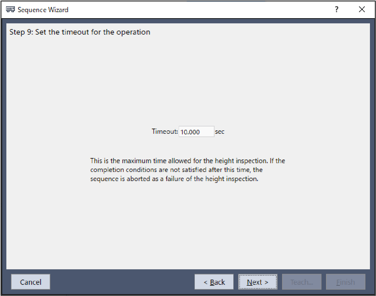
Step 6. Set the timeout for the operation
Set the time-out for the operation.
Item | Description, setting guide |
|---|---|
| Timeout | Set the time-out duration. The time-out set is the height inspect operation execution time. If the height inspect operation fails to complete even when the timeout elapses, the height inspect operation will be aborted in failure. Minimum value: 0.1 [sec] Maximum value: 60 [sec] Default: 10.0 [sec] |
| [Cancel] button | Cancels a new HeightInspect sequence creation. Click it to end a sequence wizard. |
| [Back] button | Returns to the previous Step. |
| [Next] button | You can proceed to the Change Summary screen. When you open from the new sequence creation screen, you can proceed to the Finish screen. |
| [Finish] button | You cannot click this button. |
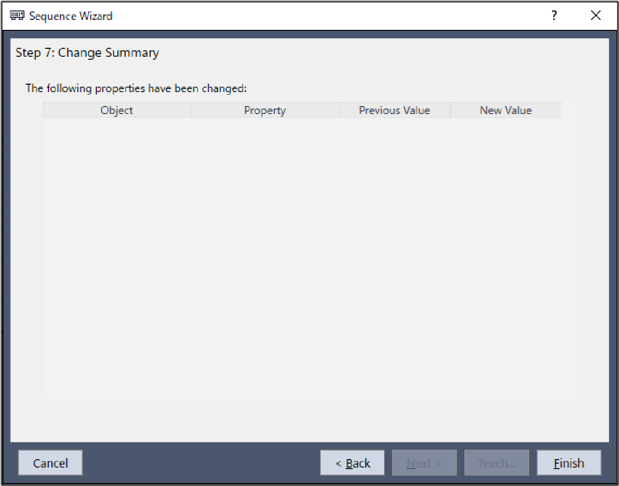
Step 7. Change Summary
You can see the list of properties that have been changed in the wizard.
This is displayed when you edit the created HeightInspect sequence in the Sequence Wizard. It is not displayed when creating a new one.
Item | Description |
|---|---|
| Object Property | Shows which properties of which sequence or object have been changed as a result of changing settings in the wizard. |
Previous Value New Value | Shows how the properties have been changed as a result of changing the settings in the wizard. |
| [Cancel] button | Cancels a new HeightInspect sequence creation. Click it to end a sequence wizard. |
| [Back] button | Returns to Step 6. |
| [Next] button | You cannot click this button. |
| [Finish] button | Completes changing the HeightInspect sequence with the entered contents. |
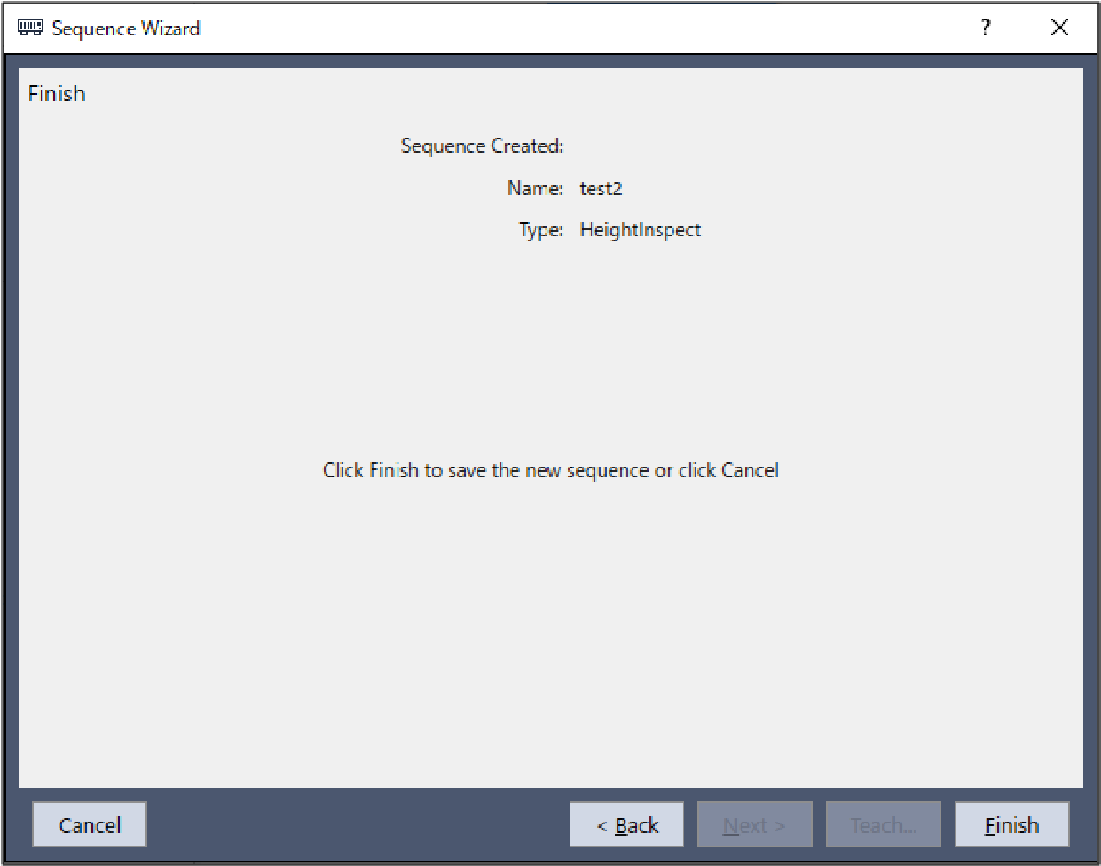
Finish: Height Inspect Sequence Created
This is the completion screen for the set sequence. You can check the created sequence name and type. The screen is displayed when opening from the new sequence creation screen.
Item | Description |
|---|---|
| Name | The sequence name set in Step 1. General. Refer to the next section for setting the sequence name. Software [Force Guidance] [Tools] menu - Create a new force guide sequence - Sequence Wizard: Create a new system force guide sequence - Step1: General |
| Type | The sequence type set in Step 3. Select system sequence. Refer to the next section for selecting the sequence type. Software [Force Guidance] [Tools] menu Create a new force guide sequence - Sequence Wizard: Create a new system force guide sequence -Step 3: Select system sequence |
| [Cancel] button | Cancels a new HeightInspect sequence creation. Click it to end a sequence wizard. |
| [Back] button | Returns to Step 6. |
| [Next] button | You cannot click this button. |
| [Finish] button | Completes creating a new HeightInspect sequence with the entered contents. |