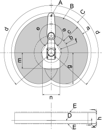
Standard Motion Range
Motion Range
The following “motion range” diagrams show the standard (maximum) specification. When each Joint motor is under servo control, the center of Joint #3’s (shaft’s) lowest point moves in the areas shown in the figure.
Area limited by a mechanical stop
The area where the center of Joint #3’s lowest point can be moved when each joint motor is not under servo control.
Mechanical stop
A stopper that sets the absolute motion range of the arm.
Maximum Range
The area that contains the farthest reach of the arms. If the maximum radius of the end effector is over 60 mm, add the “Area limited by mechanical stop” and “radius of the end effector” as the maximum area.
| A | Center of Joint #3 |
| B | Motion Range |
| C | Maximum Range |
| D | Base mounting face |
| E | Area limited by a mechanical stop |
| LS14-C60\ ** | LS14-C70\ ** | LS14-C70** | |||
|---|---|---|---|---|---|
| a | Arm #1 + Arm #2 [mm] | 600 | 700 | 800 | |
| b | Arm 1 length [mm] | 225 | 325 | 425 | |
| c | Arm 2 length [mm] | 375 | |||
| d | Joint #1 motion range [°] | 132 | |||
| e | Joint #2 motion range [°] | 150 | |||
| f | (Motion range) | 212.4 | 187.5 | 212.6 | |
| g | (Motion range of the back side) | 525.6 | 592.5 | 659.4 | |
| h | (Joint #3 motion range) | LS14-C**2S | 200 | ||
| LS14-C**3S | 300 | ||||
| LS14-C**2C | 170 | ||||
| LS14-C**3C | 270 | ||||
| i | (Distance from the base mounting face) | LS14-C**2\ * | 53 | ||
| LS14-C**3\ * | 153 | ||||
| j | (Joint #3 Mechanical stop area, upper terminal) | Standard model | 6 | ||
| Cleanroom specification | 1 | ||||
| k | (Joint #3 Mechanical stop area, lower terminal) | 5.5 | |||
| m | Rear side prohibited area Y | Standard model | 430 | 310 | 260 |
| Cleanroom specification | 430 | ||||
| n | Rear side prohibited area X | Standard model | 240 | 250 | 240 |
| Cleanroom specification | 290 | ||||
Standard & Cleanroom Environment Specification