Property setting guidelines for general sequence
General setting steps and setting methods for each property are as follows:
Step 1. Set basic information
Set properties (Name, Description, RobotNumber, AutoStepID) related to the basic information.
Properties | Description |
|---|---|
| Name | Force guide sequence name. Set a particular name. |
| Index | Particular number for a force guide sequence. It is assigned automatically. You cannot set this. |
| Description | Descriptions for force guide sequence. Describe the tasks. Set a character string. |
| Version | A compatible version of the sequence. The sequence operates with the specified version function. |
| RobotNumber | Robot number to execute a force guide sequence. Set a robot number to be executed. |
| RobotType | Robot type which is set by RobotNumber. You cannot set this. |
| AutoStepID | Set whether to set StepID of force guide object automatically. StepID is an ID which is recorded in the log data. It helps you to understand which log data support a process. True: Normal False: When you want to set StepID manually. |
Step 2. Set for correction of sensor value
Set properties (ResetSensor, MPNumber) related to sensor value correction.
Properties | Description, setting guide |
|---|---|
| ResetSensor | Set whether to reset the Force Sensor when executing a force guide object other than Decision object and SPELFunc object for the first time during the force guide sequence execution. |
True: When a workpiece has not been in contact with anything at the start of the force guide sequence. (Normally, it is in the non-contact state at the start of the force guide sequence.) | |
| False : Used in rare cases, such as when a force guide sequence is executed, and then another force guide sequence is executed with the contact state unchanged. | |
| MPNumber | Specify the number of Mass Property Object which is used during the force guide sequence execution. Mass Property Object is a collection of properties using for gravity compensation. |
| "0": When the orientations (U, V, W) do not change largely during the force guide sequence execution. | |
| Created Mass Property number: When the orientations change greatly during the force guide sequence execution. | |
For more details on Mass Property, refer to the following section. Software Gravity Compensation |
Step 3. Set for coordinate system of force control function
Set properties (ForceOrient, RobotLocal, RotationCenterType, RotationCenterTLX, RotationCenterTLY, RotationCenterTLZ) related to a coordinate system of the force control function.
Properties | Description, setting guide |
|---|---|
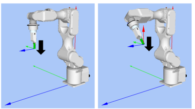
| ForceOrient | Set a coordinate system direction which executes the force control function. |
Base, Local: When you want to execute the force control function to a defined direction as viewed from outside, such as pressing to vertical-downward, even if the start orientation of force guide sequence is changed. Local is specified when a defined direction is different from the axis of the Base coordinate system. The following is an example to set Base. When pressing to -Z direction, the robot always presses to the vertical-downward (-Z direction in Base coordinate system) even the orientation of end effector changed. (Black arrow is a direction of the robot motion.)
| |
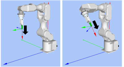
Tool: When you want to execute the force control function depending on an orientation at the start. The following is an example to set Tool. When pressing to +Z direction, the pressing direction changes depending on the orientation of end effector at the start.
| |
| RobotLocal | Set Local coordinate system number which is used when ForceOrient is Local. |
| RotationCenterType | Set a type of the rotation center setting when executing the force control function. |
Relative: As shown in the following image, when an origin of Tool coordinate system is far from a contact point: We recommend setting a rotation center of the force control function to the contact point. However, basically be sure to set Tool coordinate system so that the contact point will be an origin of Tool coordinate system.
| |
CurrentTool: When the origin of Tool coordinate system and the contact point are close or the force control function in the rotational direction is not used during the force guide sequence execution. | |
| RotationCenterTLX | When RotationCenterType is Relative, set an offset amount to each axis from Tool coordinate system to the rotation center. |
| RotationCenterTLY | |
| RotationCenterTLZ |

You can check the settings related to the coordinate system of the force control function by using a simulator. However, if no force guide object is aligned in the force guide sequence, check the setting after adding the force guide objects.
For details on how to check by using simulator, refer to the following manual.
"Epson RC+ 8.0 User's Guide: - Simulator - Description of Functions"
Step 4. Set the maximum speed and the maximum acceleration
Set properties (LimitAccelS, LimitAccelR, LimitSpeedS, LimitSpeedR) related to the maximum speed and the maximum acceleration.
Properties | Description, setting guide |
|---|---|
LimitSpeedS LimitSpeedR | Set a maximum speed during the execution of the force guide sequence. LimitSpeedS: Maximum translational speed LimitSpeedR: Maximum rotational rotation speed In the force control function, the speed changes depending on the how the force is applied. It is controlled not to exceed LimitSpeedS and LimitSpeedR. |
LimitAccelS LimitAccelR | Set a maximum acceleration during the execution of the force guide sequence. LimitAccelS: Maximum translational acceleration LimitAccelR: Maximum rotational rotation acceleration In the force control function, the acceleration changes depending on how the force is applied. It is controlled not to exceed LimitAccelS and LimitAccelR. If the value is small, reaction when the force is applied will be slow and the robot will bounce largely. Set a larger value when the robot bounces. When the robot vibrates, set the value smaller. |
Step 5. Set conditions about recording
Set properties (LogRobotLocal, LogFileEnabled, LogFileAutoName, LogFileNameVar, LogFileMaxTime, LogFileInterval) related to recording.
Properties | Description, setting guide |
|---|---|
| LogRobotLocal | Set a Local coordinate system number which will be a reference of the recording robot position. Log data related to positions is recorded as positions of the specified Local coordinate system. |
| Base: Normal | |
| Local coordinate system number: When you want to record as a position in the specified Local coordinate system | |
| LogFileEnabled | Set whether to save the log data which is executing a force guide sequence to a file. |
False: It is not saved in a file. You can check the log data on the graph of force guide window when executing. | |
| LogFileAutoName | Set whether to set the log data file name automatically. |
True : When Automatically set Is generated by the force guide sequence name and the start time. "Force guide sequence name_yyyymmdd_hh:mm:ss:ms" | |
| False: When specifying a name | |
| LogFileNameVar | Set a global variable which indicates a log data file name when LogFileAutoName is False. |
| LogFileInterval | Set a sampling interval of log data when creating files. |
| LogFileMaxTime | Set a maximum time of log data when creating files. |
Step 6. Set about checking of start position
Set properties (PointFile, RobotTool, PosCheckEnabled, OrientCheckEnabled, StartCheckPoint, StartPointTolLocal, StartPointTolX, StartPointTolY, StartPointTolZ, StartPointTolRot) related to the checking of start position.
Properties | Description, setting guide |
|---|---|
| PointFile | Set a point file which will be used in a force guide sequence. An error occurs when the specified point file is not loaded at the start. This is a property for preventing a wrong operation. If a point file is not set, any point file whichever loads is executed. |
| RobotTool | Set a tool number which will be used in a force guide sequence. An error occurs when the set tool number is not selected at the start. This is a property for preventing a wrong operation. |
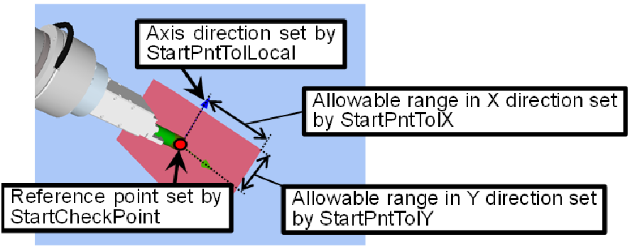
| PosCheckEnabled | Set whether to check that the position (X, Y, Z, U, V, W) at the start is within the specified range. When the robot moves after detecting a start position by using Vision, check that the position is within the range. When it is out of the range, the force guide sequence ends as failure. Error is not caused. When it failed, a recovery such as moving to other start position is available. The following is an image of setting a range. Red part is an allowable range. Set ranges for each property. Also, though it is not shown in the following image, set the allowable ranges in Z direction and rotational direction by StartPntTolZ and StartPntTolRot.
True : When checking the position and orientation |
| OrientCheckEnabled | Set whether to check that the arm orientation (Hand, Elbow, Wrist) at the start is matched the set state. When the robot moves after detecting a start position by using Vision, you can check that the arm orientation is the assumed one. When the arm orientation is not matched, the force guide sequence ends as failure. Error is not caused. When it failed, a recovery such as moving to other start position is available. True : When checking the arm orientation |
| StartCheckPoint | Set a point number which will be a reference for checking the position or the arm orientation at the start. |
| StartPntTolLocal | When PosCheckEnabled is True, set a Local coordinate system number which will be a reference of the allowable error direction. Only the axis direction is used. The origin position in Local coordinate system does not affect. |
| StartPntTolX | Set an allowable range in each direction in Local coordinate system specified by StartPntTolLocal. In X direction, an allowable range is a reference position ±StartPntTolX. The allowable range in Y and Z directions are the same way. |
| StartPntTolY | |
| StartPntTolZ | |
| StartPntTolRot | Set an allowable range of the rotational direction. The allowable range is a reference orientation ±StartPntTolRot. It is set for all U, V, and W directions. |