Sequence Wizard for an Insert Sequence
Use the sequence wizard to create an Insert sequence. This sequence wizard can be displayed by doing the following.
- Right click the sequence flow in the flowchart, or the sequence node in the sequence tree, and then select [Sequence Wizard].
- Click
 shown to the right of the [Click to open->] Wizard setting in the Insert sequence property.
When the sequence wizard appears, configure settings as instructed on the screen.
The sequence wizard for an Insert sequence can also be configured on the new sequence screen for creating a new force guide sequence. For the details, refer to the following section.
Software [Force Guidance] [Tools] menu
- Create a new force guide sequence - Sequence Wizard, Create a new system force guide sequence
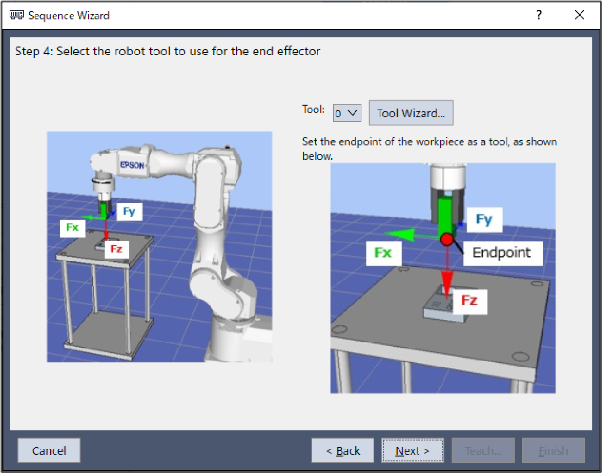
Step 1. Select the robot tool to use for the end effector
Select the tool number to be used for the Insert sequence, Insert object, and TensileTest object.
Item | Description, setting guide |
|---|---|
| Tool | Select the tool number to be used. Select a tool number so that the end point of the workpiece is at the tool origin point. Tool numbers set are sorted in the list. To set a new tool, use the Tool Wizard button. "Epson RC+ 8.0 User's Guide - Epson RC+ 8.0 GUI - [Tools] menu, [Tools] - [Robot Manager] - [Tool Settings] panel" Minimum value: 0 Maximum value: Maximum value for the set tool number Default: 0 |
| [Cancel] button | Cancels a new Insert sequence creation. Click it to end a sequence wizard. |
| [Back] button | When opening from the new sequence creation screen, you can return to the previous Step. |
| [Next] button | Proceeds to the next Step. |
| [Finish] button | You cannot click this button. |
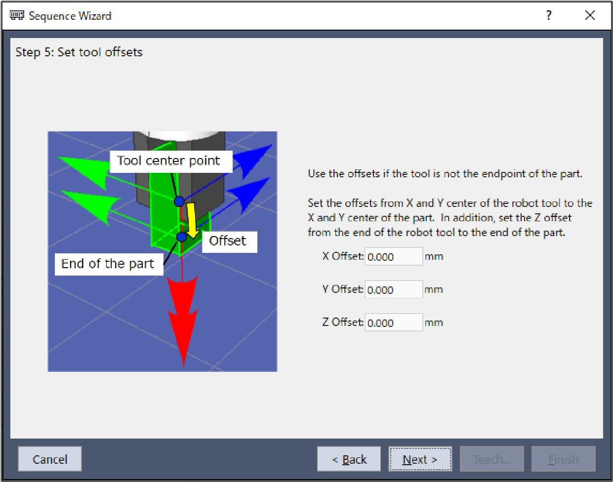
Step 2. Set tool offsets
When the tool set in Step 1 is not set in the center of the workpiece tip, this setting is required. Set the offset amount from the tool to the center of the workpiece tip.
Item | Description, settings guide |
|---|---|
| X Offset | Sets the offset amount in the X direction from the tool set in Step 1 to the tip of the workpiece. Minimum value: -2000.000 [mm] Maximum value: 2000.000 [mm] Default: 0.000[mm] |
| Y Offset | Sets the offset amount in the Y direction from the tool set in Step 1 to the tip of the workpiece. Minimum value: -2000.000 [mm] Maximum value: 2000.000 [mm] Default: 0.000[mm] |
| Z Offset | Sets the offset amount in the Z direction from the tool set in Step 1 to the tip of the workpiece. Minimum value: -2000.000 [mm] Maximum value: 2000.000 [mm] Default: 0.000[mm] |
| [Cancel] button | Cancels a new Insert sequence creation. Click it to end a sequence wizard. |
| [Back] button | Returns to the previous Step. |
| [Next] button | Proceeds to the next Step. |
| [Finish] button | You cannot click this button. |
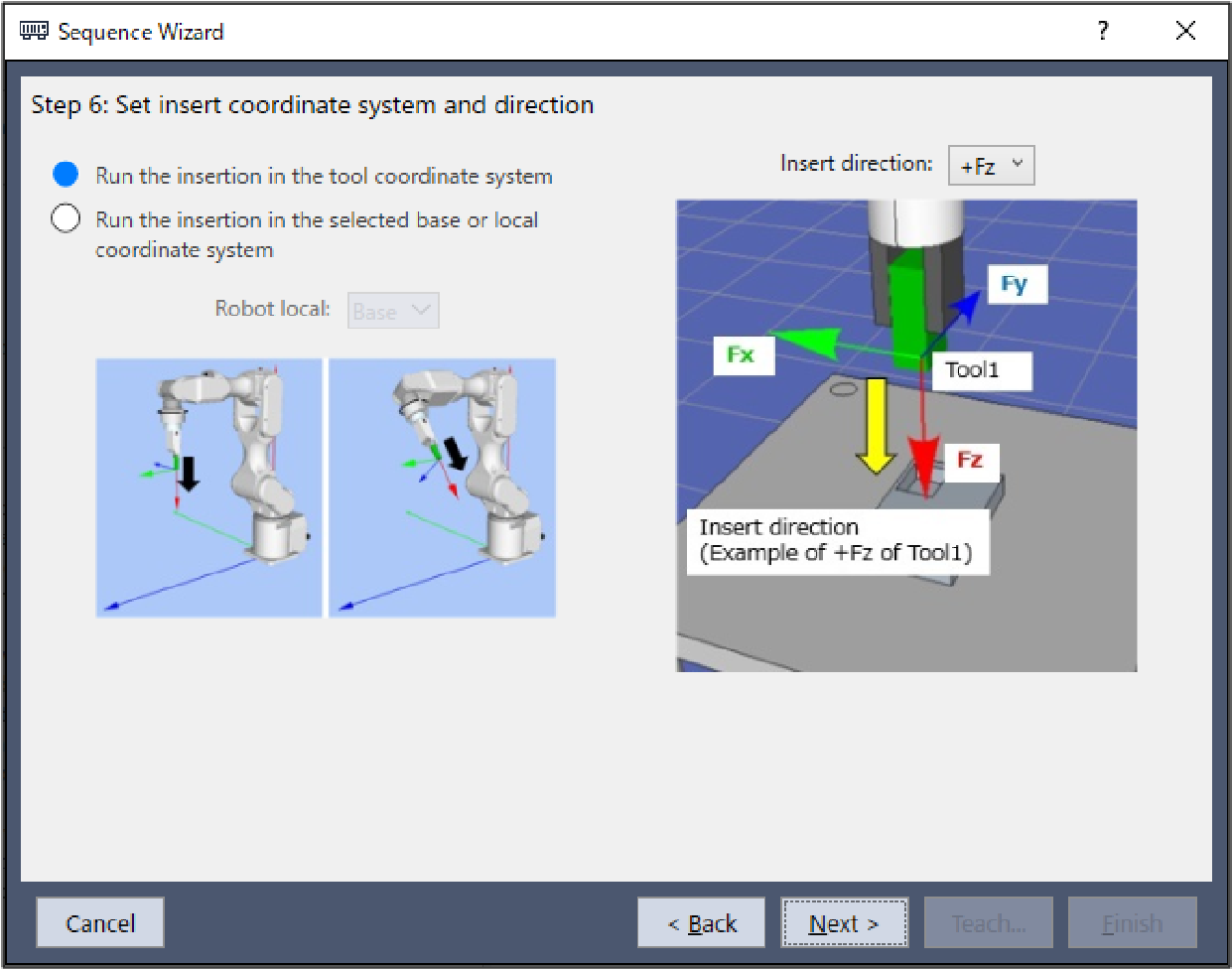
Step 3. Set insert coordinate system and direction
Set the insert direction.
Select "Tool" to perform the insert operation that matches the orientation when starting the sequence.
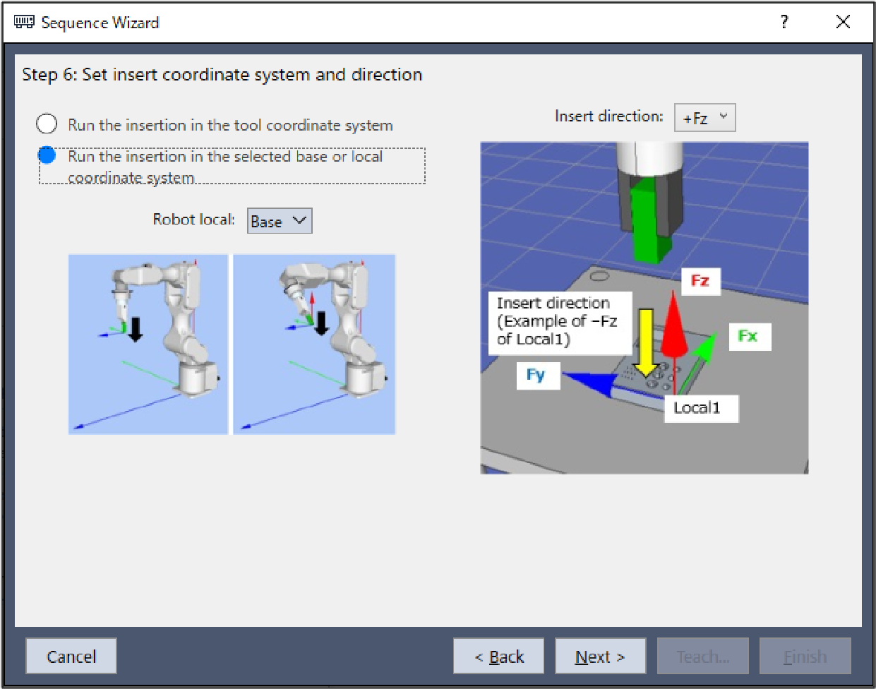
Select "Base or Local" to perform the insert operation in the direction that matches the workpiece regardless of the orientation when starting the sequence.
Item | Description, setting guide |
|---|---|
| Robot local | Select the coordinate system used by the Insert sequence. When the insert coordinate system is set to "Base" or "Local", the robot will move in the corresponding coordinate system. Select the coordinate system according to the orientation of the workpiece being inserted. Minimum value: Base (0) Maximum value: 15 Default: Base |
| Insert direction | Select the direction of insertion. When the insert coordinate system is set to "Tool", the Insert sequence and Insert object will move in the direction of insertion selected for the tool coordinate system set in Step 1. When the insert coordinate system is set to "Base" or "Local", the Insert sequence and Insert object will move in the direction of insertion selected for the base or local coordinate system set as the coordinate system. The TensileTest object will move in the opposite positive or negative direction of the direction of insertion selected. Values: +Fx, -Fx, +Fy, -Fy, +Fz, -Fz Default: +Fz |
| [Cancel] button | Cancels a new Insert sequence creation. Click it to end a sequence wizard. |
| [Back] button | Returns to the previous Step. |
| [Next] button | Proceeds to the next Step. |
| [Finish] button | You cannot click this button. |
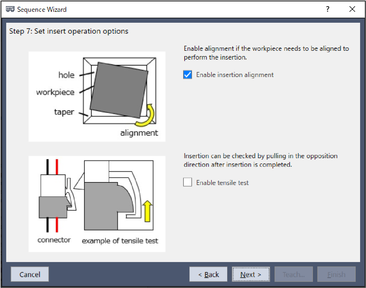
Step 4. Set insert operation options
Select whether to enable insertion alignment and tensile tests.
Item | Description, setting guide |
|---|---|
| Enable insertion alignment | Set whether to enable alignment between the workpiece and the hole. When enabled, the workpiece is aligned in the direction of the yellow arrow depicted in the top image in the wizard while the insert operation is in progress. Enable this for rectangular cylinder workpieces and other workpieces that cannot be inserted without being properly aligned. Default: Enabled |
| Enable tensile test | Set whether to perform a tensile test. Use this to determine whether a connector, or a similar workpiece, has been properly inserted by applying force in the opposite direction to the direction of insertion. Default: Disabled |
| [Cancel] button | Cancels a new Insert sequence creation. Click it to end a sequence wizard. |
| [Back] button | Returns to the previous Step. |
| [Next] button | Proceeds to the next Step. |
| [Finish] button | You cannot click this button. |
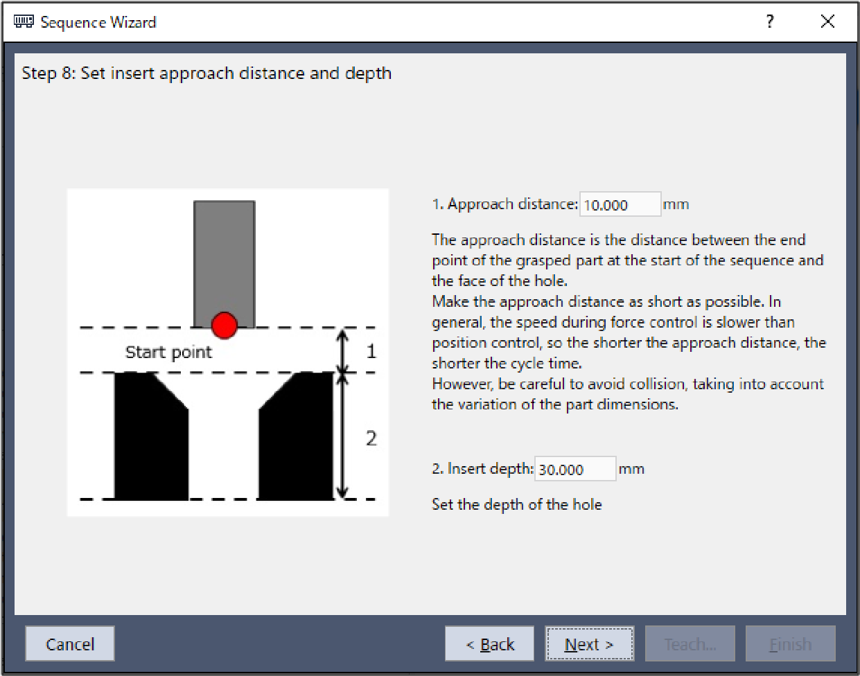
Step 5. Set insert approach distance and depth
Set the approach distance and depth for insertion.
Item | Description, setting guide |
|---|---|
| Approach distance | Set an approach distance. The approach distance is distance 1 depicted in the diagram below, which is the distance between the end point of the gripped workpiece at the start of the Insert sequence indicated by the green dot in the diagram, and the opening of the hole. Teach the robot a start point of the motion that shortens the approach distance as much as possible. As the force control function is slower than position control, longer approach distances will result in longer cycle times.
Minimum value: 0 [mm] Maximum value: 50 [mm] Default: 10[mm] |
| Insert depth | Set an insert depth. The insert depth is length 2, the depth of the hole part of the approach distance as depicted in the diagram. Minimum value: 0 [mm] Maximum value: 300 [mm] Default: 30[mm] |
| [Cancel] button | Cancels a new Insert sequence creation. Click it to end a sequence wizard. |
| [Back] button | Returns to the previous Step. |
| [Next] button | Proceeds to the next Step. |
| [Finish] button | You cannot click this button. |

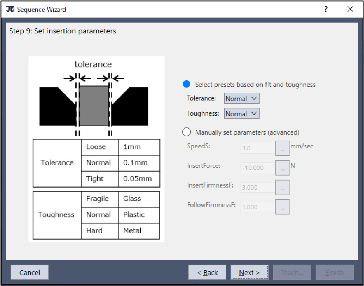
Step 6. Set insertion parameters
Set insertion parameters from the presets provided. While this property setting can be configured directly, this is for advanced users.
Item | Description, setting guide |
|---|---|
| Tolerance | Select the tolerance between the gripped workpiece and the hole. Choose from three presets, "Loose", "Normal", and "Tight". A guideline for the different tolerance levels to choose from is provided below. Loose: 1 [mm] Normal: 0.1 [mm] Tight: 0.05 [mm] Selecting a looser tolerance will increase the insertion speed and the amount of pressing force. Conversely, selecting a tighter tolerance will reduce the insertion speed and weaken the pressing force. |
| Toughness | Select the material toughness of the workpiece and hole. Choose from three presets, "Fragile", "Normal", and "Hard". A guideline for the different levels of toughness to choose from is provided below. Fragile: Glass Normal: Plastic Hard: Metal Setting the toughness to "Fragile" will weaken the pressing force and reduce the reaction speed to force applied in the direction of insertion. Conversely, setting the toughness to "Hard" will increase the pressing force and increase the reaction speed to force applied in the direction of insertion. |
| SpeedS | Set a translational speed of the robot during insertion. Actual speed is adjusted by the force control functions. This can be set by selecting advanced settings. Press the Minimum value: 0.1 [mm/sec] Maximum value: 100 [mm/sec] Default: 3.0 [mm/sec] |
| InsertForce | Set a force to insert in the insert direction. The actual force will be greater than the force set due to friction between the workpiece and the screw hole. This can be set by selecting advanced settings. Press the |
When the direction of insertion is in the positive direction: Minimum value: -50.0 [N] Maximum value: 0.0 [N] Default: -10.0 [N] | |
When the direction of insertion is in the negative direction: Minimum value: 0.0 [N] Maximum value: 50.0 [N] Default: 10.0 [N] | |
| InsertFirmnessF | Set the firmness of the force control functions in the insert direction. |
When setting a large value: The Force Control functions become stronger, but response to changes in force is slow. | |
When setting a small value: The Force Control function will become weaker. Response to changes in force is fast; however, vibrations can easily occur. | |
This can be set by selecting advanced settings. Press the Minimum value: 0.1 Maximum value: 10 Default: 3.0 | |
| FollowFirmnessF | Set a firmness of the force control function following a translational force in a direction other than the direction of insertion. |
When setting a large value: The Force Control functions become stronger, but response to changes in force is slow. | |
When setting a small value: The Force Control function will become weaker. Response to changes in force is fast; however, vibrations can easily occur. | |
This can be set by selecting advanced settings. Press the Minimum value: 0.1 Maximum value: 10 Default: 1.0 | |
| [Cancel] button | Cancels a new Insert sequence creation. Click it to end a sequence wizard. |
| [Back] button | Returns to the previous Step. |
| [Next] button | Proceeds to the next Step. |
| [Finish] button | You cannot click this button. |
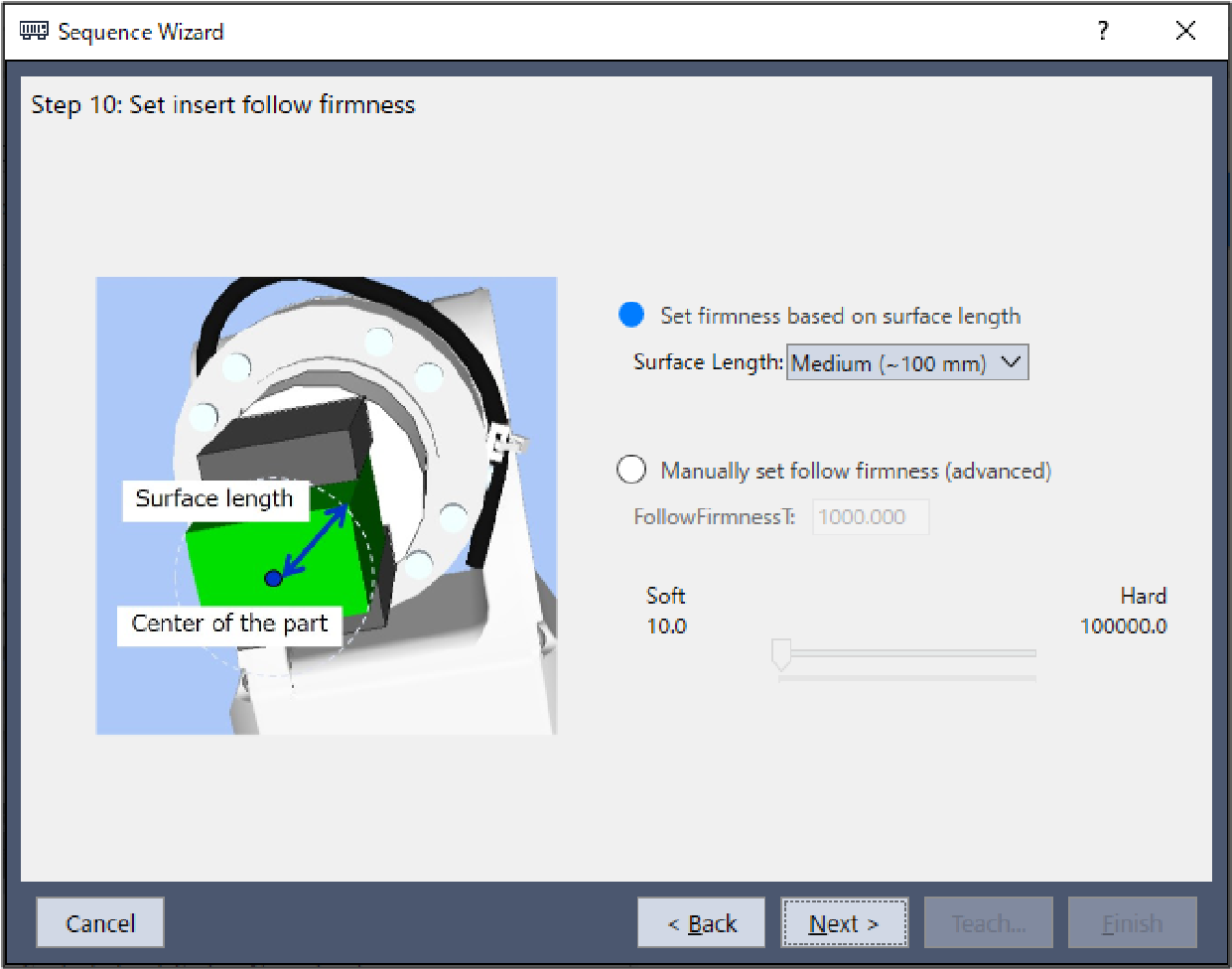
Step 7. Set insert follow firmness
Use the presets to set the firmness of the force control function following the direction of rotation. While this property setting can be configured directly, this is for advanced users.
Item | Description, setting guide |
|---|---|
| Surface Length | Select the length from the point of contact (the specified center point of the tool) to the end point of the workpiece. Choose from three presets, "Short", "Medium", and "Long". A guideline for the different tolerance levels to choose from is provided below. Short: up to 60 [mm] Medium: up to 100 [mm] Long: up to 200 [mm] The length is depicted by the blue arrow in the diagram below. This is the length of the radius of a circle from the center point (point of contact) to the most distant edge of the workpiece, thus large enough to fit the surface area of the workpiece.
The shorter this setting is, the faster the reaction following the direction of rotation. The longer this setting is, the slower the reaction following the direction of rotation. |
| FollowFirmnessT | Set a firmness of the force control functions in rotation direction. |
When setting a large value: The Force Control functions become stronger, but response to changes in force is slow. | |
When setting a small value: The Force Control function will become weaker. Response to changes in force is fast; however, vibrations can easily occur. | |
This can be set by selecting advanced settings. Press the Minimum value: 10.0 Maximum value: 100000 Default: 1000 | |
| [Cancel] button | Cancels a new Insert sequence creation. Click it to end a sequence wizard. |
| [Back] button | Returns to the previous Step. |
| [Next] button | Proceeds to the next Step. |
| [Finish] button | You cannot click this button. |

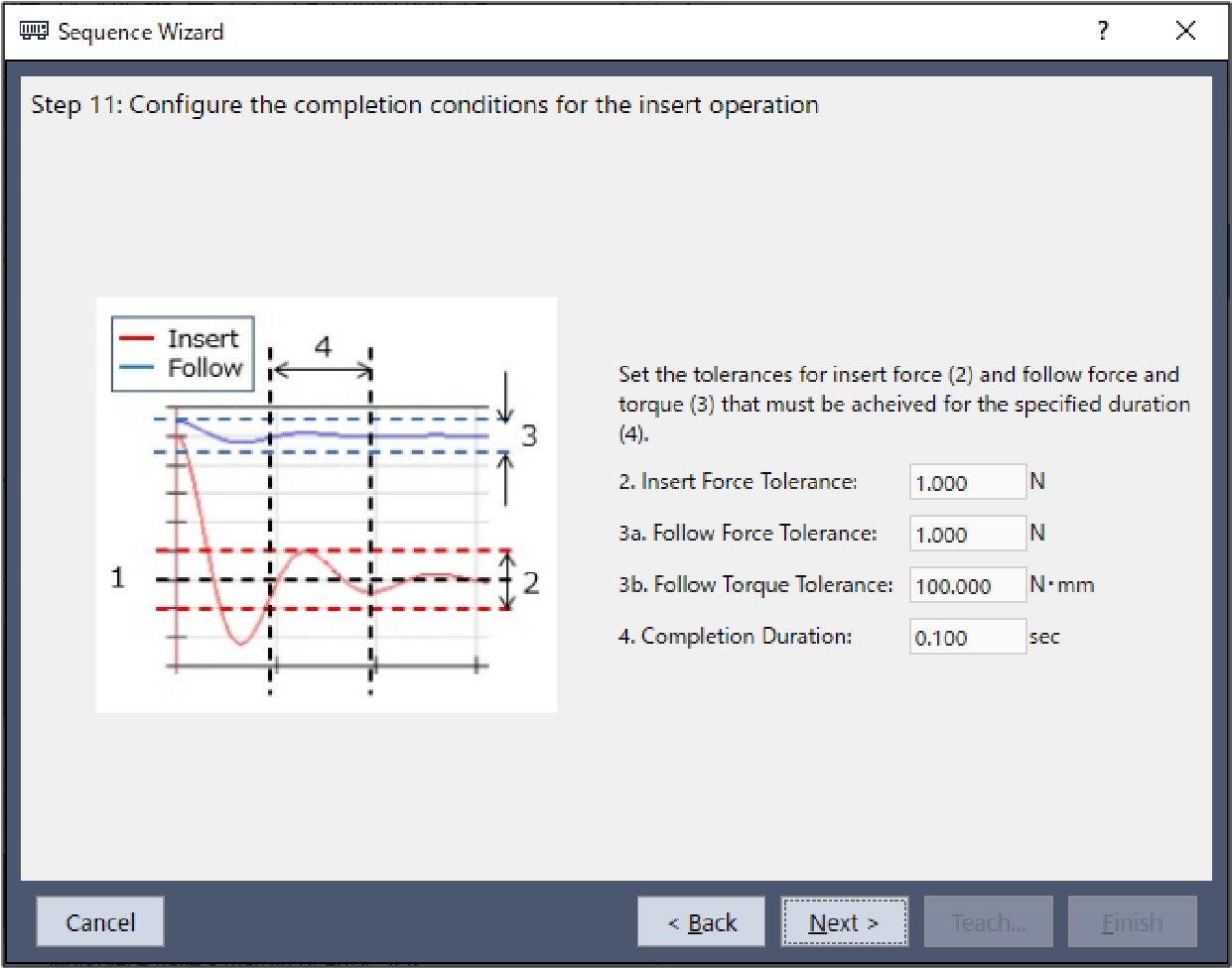
Step 8. Configure the completion conditions for the insert operation
Configure the completion conditions for the insert operation.
Item | Description, setting guide |
|---|---|
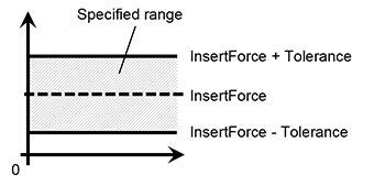
| Insert Force Tolerance | The insertion direction range for the end condition related to force. Set a range of the end conditions. This monitors whether the force in the direction specified either by the Fx, Fy, or Fz insertion direction (InsertForce) is within the InsertForce± tolerance range. For example, if the direction of insertion is set to +Fz, the force in the Fz direction will be monitored on whether its value is within this range. The following diagram provides a visual representation.
The lower this tolerance value, the stricter success conditions are for the operation. It is recommended that you increase the tolerance, and then adjust it back based on actual operation results obtained. Minimum value: 0.1 [N] Maximum value: 10 [N] Default: 1.0 [N] |
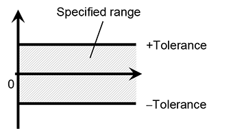
| Follow Force Tolerance | The tolerance range for following motion in a direction other than the direction of insertion set as an end condition related to force. Set a range of the end conditions. This monitors whether the force in a direction other than that specified either by the Fx, Fy, or Fz insertion direction is within the tolerance range. For example, if the direction of insertion is set to +Fz, the force in the Fx and Fy directions will be monitored on whether its value is within this range. The following diagram provides a visual representation.
The lower this tolerance value, the stricter success conditions are for the operation. It is recommended that you increase the tolerance, and then adjust it back based on actual operation results obtained. Minimum value: 0.1 [N] Maximum value: 10 [N] Default: 1.0 [N] |
| Follow Torque Tolerance | Set the range to use as the end condition related to torque. This monitors whether the torque represented by Tx, Ty, or Tz is within the tolerance range. However, note that torque around the direction of insertion is only monitored when enabling insertion alignment in Step 4. For example, if the direction of insertion is set to +Fz and insertion alignment is enabled, the torque in the Tx, Ty, Tz directions will be monitored on whether its value is within this range. If insertion alignment is disabled, only torque in the Tx and Ty directions will be monitored. Torque in the Tz direction will not be monitored. The following diagram provides a visual representation.
The lower this tolerance value, the stricter success conditions are for the operation. It is recommended that you increase the tolerance, and then adjust it back based on actual operation results obtained. Minimum value: 1 [N·mm] Maximum value: 10,000 [N・mm] Default: 100 [N・mm] |
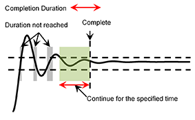
| Completion Duration | Set the duration time which is used to determine whether the end conditions have satisfied. As shown below, if the specified condition continues for the time specified by Completion Duration, it is determined as the end conditions are satisfied.
Normally, set a short time close to "0". We recommend setting the time according to the actual result. Minimum value: 0.0 [sec] Maximum value: 10 [sec] Default: 0.1 [sec] |
| [Cancel] button | Cancels a new Insert sequence creation. Click it to end a sequence wizard. |
| [Back] button | Returns to the previous Step. |
| [Next] button | Proceeds to the next Step. |
| [Finish] button | You cannot click this button. |
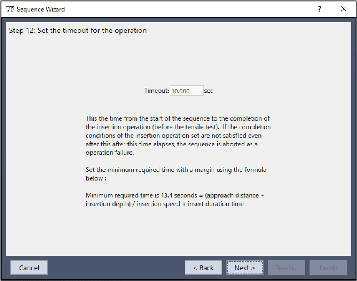
Step 9. Set the timeout for the operation
Set the time-out for the operation. It is recommended that you set a longer time than the minimum required time.
Item | Description, setting guide |
|---|---|
| Timeout | Set the time-out duration. The time-out set is the insert operation execution time. If the insert operation fails to meet the end conditions set in Step 8 even when the timeout elapses, the insert operation will be aborted in failure. The minimum required time-out duration appears in the wizard. This is the minimum time required to complete the insert operation. As such, set the time-out duration to a longer time than the minimum required time shown. The minimum required time is determined based on the approach distance, insert depth, insertion speed, and time required to determine success set in Steps 5, 6, and 8, respectively. Minimum value: 0.1 [sec] Maximum value: 60 [sec] Default: 10.0 [sec] |
| [Cancel] button | Cancels a new Insert sequence creation. Click it to end a sequence wizard. |
| [Back] button | Returns to the previous Step. |
| [Next] button | When the tensile test is disabled in Step 4, you can proceed to the Change Summary screen. When you open from the new sequence creation screen, you can proceed to the Finish screen. |
| When the tensile test is enabled in Step 4, you can proceed to the next Step. | |
| [Finish] button | You cannot click this button. |
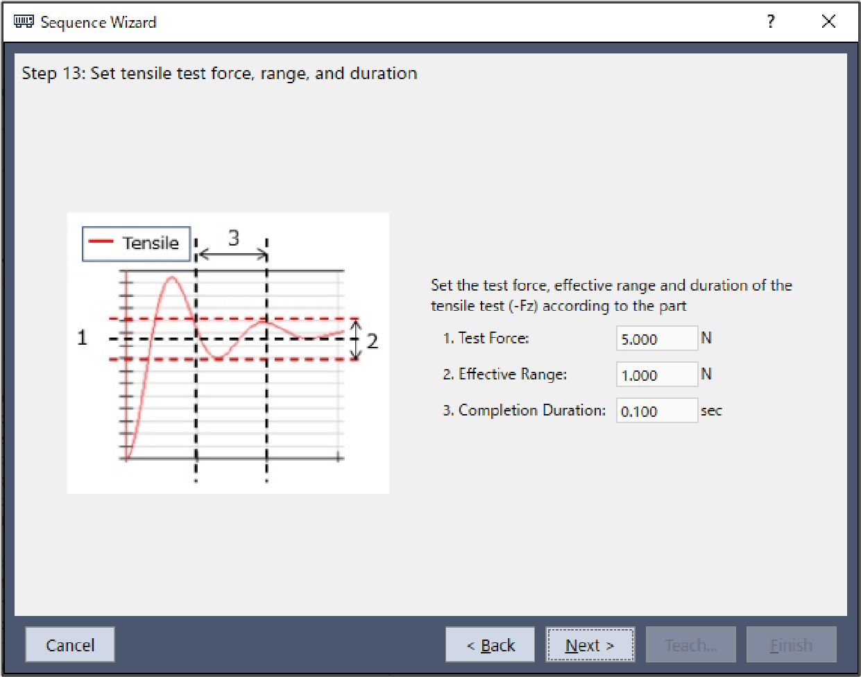
Step 10. Set tensile test force, range, and duration
Set the end conditions for the tensile test. This setting screen is displayed when the tensile test is enabled in Step 4.
Item | Description, setting guide |
|---|---|
| Test Force | Set a test force applied in the direction of the tensile test shown in the wizard. Set a test force according to the part in use. |
When the tensile test direction is in the positive direction: Minimum value: -50.0 [N] Maximum value: 0.0 [N] Default: -5.0 [N] | |
When the direction of insertion is in the negative direction: Minimum value: 0.0 [N] Maximum value: 50.0 [N] Default: 5.0 [N] | |
| Effective Range | Range of the tensile test direction of the end conditions related to force. Set a range of the end conditions. This monitors whether the force in the direction indicated either by the Fx, Fy, or Fz tensile test direction is within the +- effective range. For example, if the tensile test direction is indicated by -Fz, the force in the -Fz direction will be monitored on whether its value is within this range. The following diagram provides a visual representation.
The lower this tolerance value, the stricter success conditions are for the operation. It is recommended that you increase the tolerance, and then adjust it back based on actual operation results obtained. Minimum value: 0.1 [N] Maximum value: 10 [N] Default: 1.0 [N] |
| Completion Duration | Set the duration time which is used to determine whether the end conditions have satisfied. As shown below, if the specified condition continues for the time specified by Completion Duration, it is determined as the end conditions are satisfied.
Normally, set a short time close to "0". It is recommended that you set this duration based on actual operation results. Minimum value: 0.0 [sec] Maximum value: 10 [sec] Default: 0.1 [sec] |
| [Cancel] button | Cancels a new Insert sequence creation. Click it to end a sequence wizard. |
| [Back] button | Returns to the previous Step. |
| [Next] button | Proceeds to the next Step. |
| [Finish] button | You cannot click this button. |
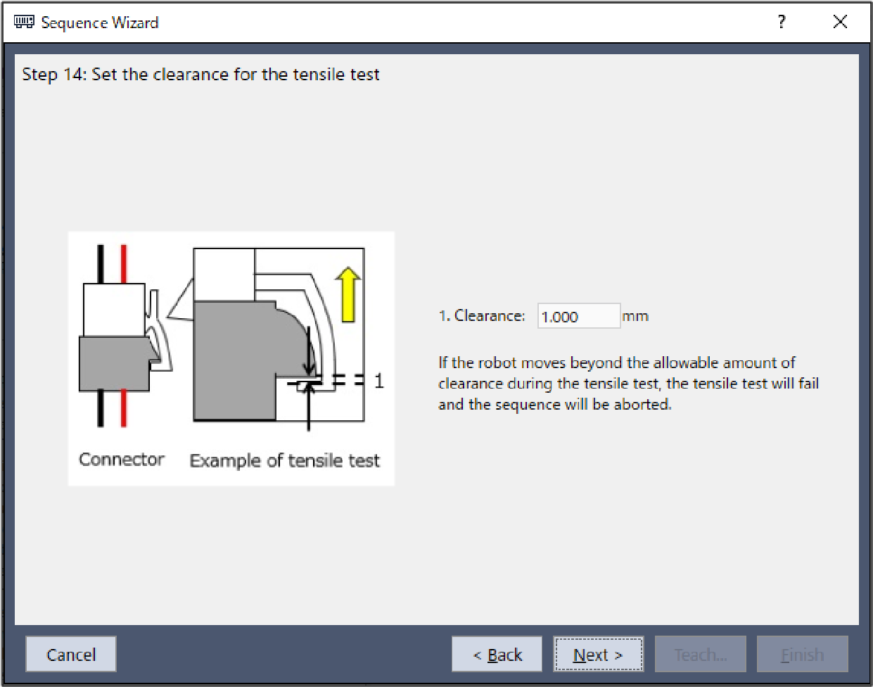
Step 11. Set the clearance for the tensile test
Set the clearance for the tensile test. This setting screen is displayed when the tensile test is enabled in Step 4.
Item | Description, settings guide |
|---|---|
| Clearance | Sets the clearance between workpieces that occurs when the workpieces are pulled. When performing a tensile test, if the robot moves the allowable amount of clearance set in the Step 10 tensile test direction display or more, the TensileTest object will fail and the will be aborted. Minimum value: 0.1 [mm] Maximum value: 10 [mm] Default: 1[mm] |
| [Cancel] button | Cancels a new Insert sequence creation. Click it to end a sequence wizard. |
| [Back] button | Returns to the previous Step. |
| [Next] button | Proceeds to the next Step. |
| [Finish] button | You cannot click this button. |
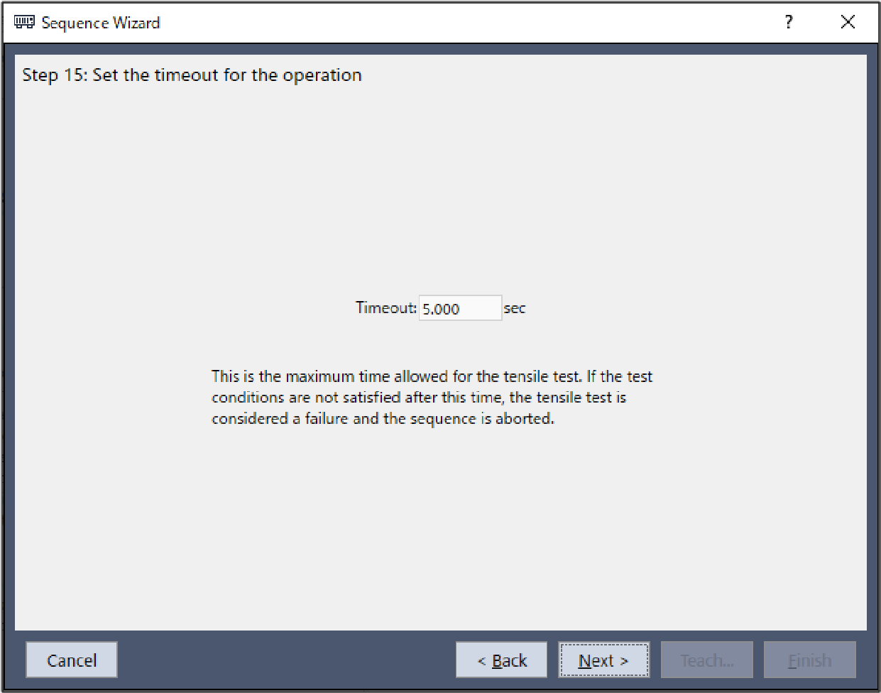
Step 12. Set the timeout for the operation
Set the time-out for the tensile test.
Item | Description, setting guide |
|---|---|
| Timeout | Set the time-out duration. The time-out set is the tensile test execution time. If the tensile test does not meet the completion condition set in Step 10 even after the set time-out has passed, the test is considered a failure and the Insert sequence is aborted. Minimum value: 0.1 [sec] Maximum value: 60 [sec] Default: 5.0 [sec] |
| [Cancel] button | Cancels a new Insert sequence creation. Click it to end a sequence wizard. |
| [Back] button | Returns to the previous Step. |
| [Next] button | Proceeds to the Change Summary screen. When you open from the new sequence creation screen, you can proceed to the Finish screen. |
| [Finish] button | You cannot click this button. |
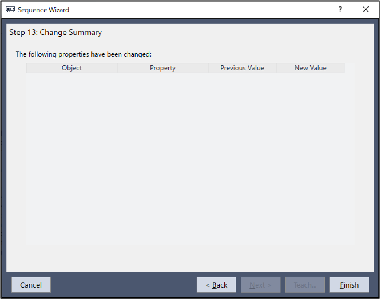
Step 13. Change Summary
You can see the list of properties that have been changed in the wizard.
This is displayed when you edit the created Insert sequence in the Sequence Wizard. It is not displayed when creating a new one.
Item | Description |
|---|---|
Objects Properties | Shows which properties of which sequence or object have been changed as a result of changing settings in the wizard. |
Previous Value New Value | Shows how the properties have been changed as a result of changing the settings in the wizard. |
| [Cancel] button | Cancels a new Insert sequence creation. Click it to end a sequence wizard. |
| [Back] button | Returns to Step 9 when the tensile test in Step 4 is disabled. |
| Returns to Step 12 when the tensile test in Step 4 is enabled. | |
| [Next] button | You cannot click this button. |
| [Finish] button | Completes changing the Insert sequence. Completes changing the Insert sequence with the entered contents. |
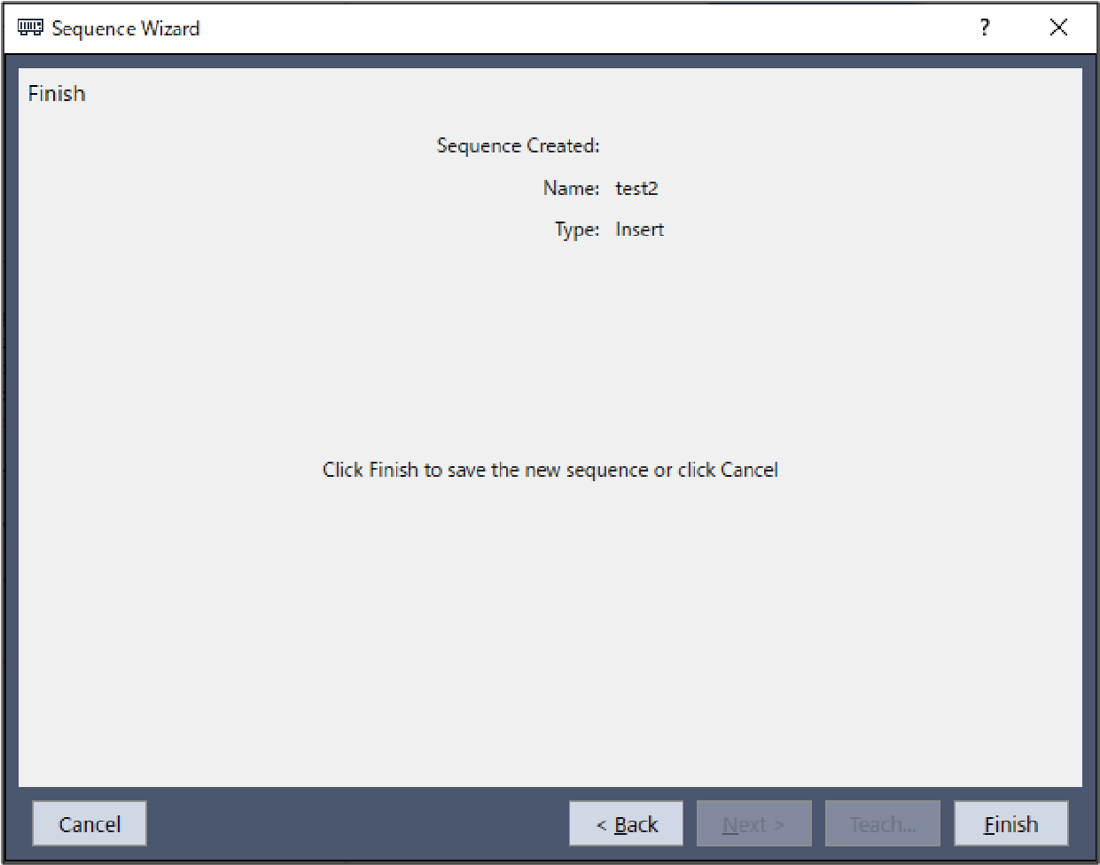
Finish: Insert Sequence Created
This is the completion screen for the set sequence.
You can check the created sequence name and type. The screen is displayed when opening from the new sequence creation screen.
Item | Description |
|---|---|
| Name | The sequence name set in Step 1. General. Refer to the next section for setting the sequence name. Software [Force Guidance] [Tools] menu - Create a new force guide sequence - Sequence Wizard: Create a new system force guide sequence - Step1: General |
| Type | The sequence type set in Step 3. Select system sequence. Refer to the next section for selecting the sequence type. Software [Force Guidance] [Tools] menu Create a new force guide sequence - Sequence Wizard: Create a new system force guide sequence -Step 3: Select system sequence |
| [Cancel] button | Cancels a new Insert sequence creation. Click it to end a sequence wizard. |
| [Back] button | Returns to Step 9 when the tensile test in Step 4 is disabled. |
| Returns to Step 12 when the tensile test in Step 4 is enabled. | |
| [Next] button | You cannot click this button. |
| [Finish] button | Completes creating a new Insert sequence. Completes creating a new Insert sequence with the entered contents. |