Example of Robot Control by SRCI
An example of performing robot control from a Siemens PLC is described below.
- Use "TIA Portal V20" as the client software of Siemens PLC.
- Create a new project on the TIA Portal from the Archive file in "SIMATIC Robot Library V1.2" provided by Siemens.
- Perform robot control through SCL (Structured Control Language).
Change the setting of PLC model number to your PLC model number.
Under [Project tree], double-click [Device & networks], and then double-click [PLC_1] at the center of the screen.
Right-click the PLC shown in [Device view], and select [Change device].
Select your PLC model number, and press the [OK] button.
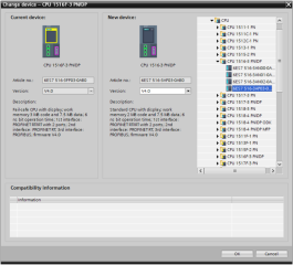
Make the settings for communication between the PLC and controller.
See below and make the settings for communication between the PLC and controller.
Setting a Siemens PLCUnder [Project tree], select [PLC_1] - [PLC_tags], and then double-click and open [RobotCommunication].
Copy and paste [Xxx_To_PLC] and [PLC_To_Xxx] defined for other companies, and then change the name.
Change the [Address] setting to the value set in the input/output module of [RC800-PROFINET-IO].
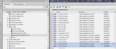
Set the RobotTask function block for Epson robot control.
Under [Project tree], create the [Epson] group below [PLC_1] - [Program blocks] - [Robots].
Under [Project tree], copy the following data blocks set in the group for other robot vendors below [PLC_1] - [Program blocks] - [Robots], paste them to the group created in i., and change the names:
AxesGroupXxx
Robot_User_Data_Xxx
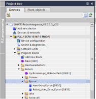
Right-click [PLC_1] and select [Compile] - [Hardware and software (only changes)]. A warning is displayed regarding duplication of the data block numbers copied in ii. Press [OK] to resolve the duplicate numbers.
From [PLC_1] - [Program blocks] - [Robots], double-click [Cyclicinterrupt_McRobotTask].
Open [Network 8], and from [PLC_1] - [Program blocks] - [SRL] - [LRob], drag & drop [MC_RobotTask_LRob], and press the [OK] button in the [Call options] dialog box.
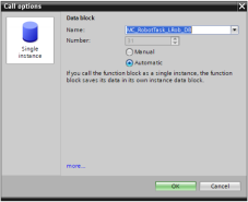
The data block configured in step v. appears under [PLC_1] - [Program blocks] - [Robots]. Move it to the [Epson] group and rename it.
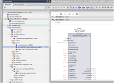
Set each parameter of the RobotTask function block.
Parameter name Data name RobotInData “Epson_To_PLC”.Arm1 RobotOutData “PLC_To_Epson”.Arm1 UserData “Robot_User_Data_Epson”.UserData ToolData “Robot_User_Data_Epson”.ToolData FrameData “Robot_User_Data_Epson”.FrameData LoadData “Robot_User_Data_Epson”.LoadData SoftwareLimit “Robot_User_Data_Epson”.SwLimits DefaultDynamics “Robot_User_Data_Epson”.DefaultDynamics ReferenceDynamics “Robot_User_Data_Epson”.ReferenceDynamics WorkArea “Robot_User_Data_Epson”.WorkAreaData MessageLog “Robot_User_Data_Epson”.MessageLog SystemLog “Robot_User_Data_Epson”.SystemLog ConstantData “Lrob_ConstantData” AxesGroup “AxesGroupEpson”
Write the SCL program for robot control.
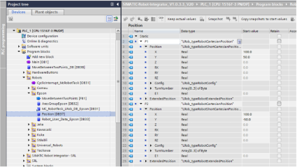
From [PLC_1] - [Program blocks] - [Robots], right-click [Epson], select [Add new block], set [Type] to Global DB, and create a data block. In the data block that is created, define two instances of data having the Data type as Lrob_typeRobotCartesianPosition, as shown in the figure below.
From [PLC_1] - [Program blocks] - [Robots], right-click [Epson], select [Add new block], set [Language] to SCL, and create the two function blocks described below.
- SrciFBs
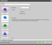
- MoveBetweenTwoPoints
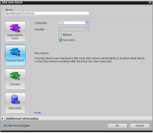
- SrciFBs
In the function blocks created in ii., define the data as shown in the figure below.
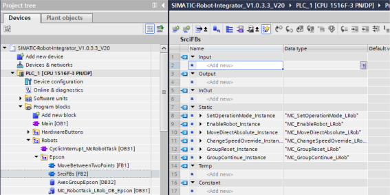
In the function block created in ii., write the following source code.
#SetOperationMode_Instance(AxesGroup := "AxesGroupEpson");
#EnableRobot_Instance(AxesGroup := "AxesGroupEpson");
#MoveDirectAbsolute_Instance(AxesGroup := "AxesGroupEpson");
#ChangeSpeedOverride_Instance(AxesGroup := "AxesGroupEpson");
#GroupReset_Instance(AxesGroup := "AxesGroupEpson");
#GroupContinue_Instance(AxesGroup := "AxesGroupEpson");
In the function blocks created in ii., define the data as shown in the figure below.
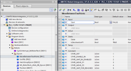
In the function block created in ii., write the following source code.
CASE #State OF
#STATE_INIT:
    IF #Start THEN
        "SrciFBs_DB".ChangeSpeedOverride_Instance.Override := 10.0;
        "SrciFBs_DB".MoveDirectAbsolute_Instance.VelocityRate := 100.0;
        "SrciFBs_DB".MoveDirectAbsolute_Instance.AccelerationRate := 100.0;
        "SrciFBs_DB".MoveDirectAbsolute_Instance.DecelerationRate := 100.0;
        "SrciFBs_DB".MoveDirectAbsolute_Instance.JerkRate := -1.0;

        "SrciFBs_DB".SetOperationMode_Instance.OperationMode := 4;
        "SrciFBs_DB".SetOperationMode_Instance.Execute := TRUE;

        "SrciFBs_DB".GroupReset_Instance.Execute := TRUE;
        #State := #STATE_ENABLE_RA;
    END_IF;

#STATE_ENABLE_RA:
    IF "SrciFBs_DB".SetOperationMode_Instance.Done THEN
        "SrciFBs_DB".EnableRobot_Instance.Enable := TRUE;
        #State := #STATE_WAIT_RA_ENABLED;
    END_IF;

#STATE_WAIT_RA_ENABLED:
    IF "SrciFBs_DB".EnableRobot_Instance.Enabled THEN
        "SrciFBs_DB".ChangeSpeedOverride_Instance.Execute := TRUE;
        "SrciFBs_DB".GroupContinue_Instance.Execute := TRUE;
        #State := #STATE_MOVE_P1;
    END_IF;

#STATE_MOVE_P1:
    "SrciFBs_DB".MoveDirectAbsolute_Instance.Position := "Position".P1;
    "SrciFBs_DB".MoveDirectAbsolute_Instance.Execute := TRUE;
    #State := #STATE_WAIT_FOR_REACHED;

#STATE_MOVE_P2:
    "SrciFBs_DB".MoveDirectAbsolute_Instance.Position := "Position".P2;
    "SrciFBs_DB".MoveDirectAbsolute_Instance.Execute := TRUE;
    #State := #STATE_WAIT_FOR_REACHED;

#STATE_WAIT_FOR_REACHED:
    IF "SrciFBs_DB".MoveDirectAbsolute_Instance.Done THEN
        "SrciFBs_DB".MoveDirectAbsolute_Instance.Execute := FALSE;
        IF #IsDestinationP1 THEN
            #State := #STATE_MOVE_P2;
        ELSE
            #State := #STATE_MOVE_P1;
        END_IF;
        #IsDestinationP1 := NOT #IsDestinationP1;
    END_IF;

    IF NOT #Start THEN
        "SrciFBs_DB".SetOperationMode_Instance.Execute := FALSE;
        "SrciFBs_DB".EnableRobot_Instance.Enable := FALSE;
        "SrciFBs_DB".ChangeSpeedOverride_Instance.Execute := FALSE;
        "SrciFBs_DB".GroupReset_Instance.Execute := FALSE;
        "SrciFBs_DB".GroupContinue_Instance.Execute := FALSE;
        #State := #STATE_INIT;
    END_IF;
END_CASE;
From [PLC_1] - [Program blocks], double-click and open [Main], drag & drop the function blocks that were created to [Network 1], and then press the [OK] button in the dialog box that is displayed.
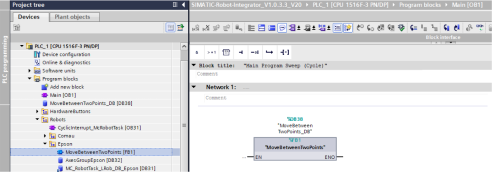
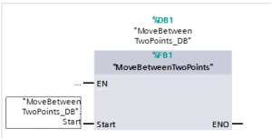
From [PLC_1] - [Program blocks], change the "Start" parameter of the function block "MoveBetweenTwoPoints" set in [Main] to ""MoveBetweenTwoPoint_DB".Start".
Operate the robot using the project that is created.
Right-click [PLC_1] and select [Compile] - [Hardware and software (only changes)].
Right-click [PLC_1] while the PC and the PLC are connected, select [Download to device] - [Hardware and software (only changes)], and update the hardware settings and software settings of the PLC unit.
Press either the [Run] button on the PLC unit or the [Start CPU] button on the TIA Portal to start the program on the PLC.
From [PLC_1] - [Program blocks], open [Main], and then press the [Monitoring on/off] button to enable monitoring.
Right-click "Start" for the "MoveBetweenTwoPoints" function block, and then select [Modify] - [Modify to 1]. The state transition of the [MoveBetweenTwoPoints] function block starts, and the robot operates.
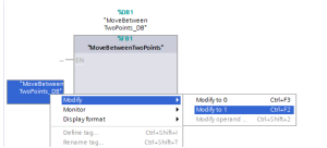
Right-click "Start" for the "MoveBetweenTwoPoints" function block, and then select [Modify] - [Modify to 0] to stop the robot operation.