Setting a Siemens PLC
This section describes the procedure of making PLC settings when connecting to a Siemens PLC. For the detailed contents, refer to the manual provided by the vendor.
Make the PLC settings according to the procedure below.
We will explain this procedure using the example below.
- Use "TIA Portal V20" as the client software of Siemens PLC.
Import the basic performance information of the fieldbus module (PROFINET Slave Module).
Select [Options] - [Manage general station description files(GSD)].
In [Source path:] in the [Manage general station description files] dialog box, specify the Fieldbus\PROFINET folder below the RC+ installation folder. If RC+ is installed with the default settings, the folder will be [C:\EpsonRC80\Fieldbus\PROFINET].
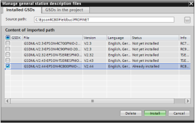
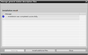
Place a check mark at [GSDML-V2.44-EPSON-RC800PNIO-20240410.xml] in the file list displayed under [Content of imported path], and press the [Install] button.
Check the name and address of the fieldbus module, and change the settings, if necessary.
Turn the controller ON.
Connect the Ethernet port of the PC on which the TIA Portal is installed to the fieldbus module of the controller using an Ethernet cable.
On the TIA Portal, open [Online access] under [Project tree], and then open the tree of the device name indicating the PC Ethernet.
Double-click [Update accessible devices].
A tree containing the PROFINET device name and IP address (Example: [rc800-profinet-io [192.168.1.3]]) will be displayed.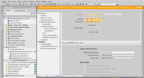
Set the PROFINET device name and IP address according to your network configuration.
Once the setting is complete, pull out the Ethernet cable from the PC.
Make the settings for communication between the PLC and the fieldbus module.
Under [Project tree], open [Devices & network].
Open the tree of [Hardware catalog], and from [Other field devices] - [PROFINET-IO] - [General] - [SEIKO EPSON CORPORATION] - [RC800-PROFINET-IO], drag & drop [RT RC800_PNIO_V2] to the center of the screen.
The device added here is the PROFINET interface of the controller.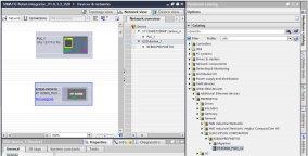
Select the interface part (green square in the figure) of [RC800-PROFINET-IO] dropped in ii., and set the PROFINET device name and IP address set in step ②.
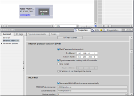
Connect the PLC and PROFINET interface.
Drag the interface part of the PLC and drop it to the interface part of [RC800-PROFINET-IO].
Set the PROFINET device name and IP address of the connected PLC's PROFINET interface so that it can communicate with the interface configured in iii.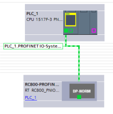
Set the communication width of the fieldbus, and then set the I/O address to be used for communication.
Double-click the figure of [RC800-PROFINET-IO] to open [Device view].
Under [Hardware catalog], open [Module] - [Output modules], and then drag & drop the input module to [Device overview].
If the output bytes of the controller's fieldbus slave are 256 bytes, you can configure a 256-byte width input by dragging and dropping one [Output 32 bytes] into [Device overview], changing the value of [Q address] to the desired address, and copying and pasting the [Output 32 bytes_1] record seven times.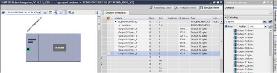
Similar to ii., under [Hardware catalog], open [Module] - [Input modules], and then drag & drop the output module to [Device overview].
If the input sizes of the controller's fieldbus slave are 256 bytes, you can configure a 256-byte width input by dragging and dropping one [Input 32 bytes] into [Device overview], changing the value of [I address] to the desired address, and copying and pasting the [Input 32 bytes_1] record seven times.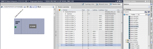
Set the data block in which the I/O address specified in 4. is set to the RobotInData and RobotOutData of the RobotTask function block.
See below for a setting example.
Example of Robot Control by SRCI