Getting started
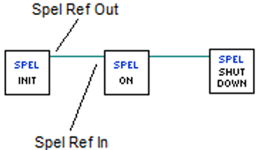
To use the LabVIEW VI library, your application must first call the Spel Initialize VI for each Controller you want to use. The Initialize VI starts an Epson RC+ 8.0 server process that will connect to the Robot Controller and process the subsequent Spel command VIs. The Initialize VI has a Spel Ref Out output. This must be wired to the next Spel VI Spel Ref In input. Then for each subsequent VI, the Spel Ref Out output from a previous Spel VI must be wired to the Spel Ref In input of the next Spel VI.
For example, the flow diagram below shows the wires for Spel Ref Out and Spel Ref In between each Spel node.
When the application is shutting down, you must call the Spel Shutdown VI. This will disconnect from the Robot Controller and shutdown the associated Epson RC+ 8.0 server process.
Follow these steps to get started. First, you will create two safe robot points from within the Epson RC+ 8.0 GUI for the LabVIEW default Spel+ project. Then you will build a small application in LabVIEW to move the robot between the two points.
Ensure that the Epson RC+ 8.0 and the Epson RC+ 8.0 LabVIEW VI Library are installed on your PC. See section for details for installing the LabVIEW VI Library.
InstallationStart Epson RC+ 8.0.
From the Project menu, select Open, then navigate to the LabVIEW folder and select the LabVIEW_Default project. Click Open.
From the Tools menu, select Robot Manager. Click the Motor On button.
Select the Jog & Teach page on the Robot Manager. Jog the robot to some safe position.
Click Teach to teach point 0.
Jog the robot to another safe position.
Select P1 from the Point list, then click Teach to teach point 1.
Click the Save button on the main toolbar to save the points.
Close Epson RC+ 8.0.
Start LabVIEW and create a new VI.
Open the block diagram for the new VI.
From [Epson Robots 8.0] - [System] tool palette, drag an Init VI onto the block diagram. The Initialize VI is required for each Controller that you interface with.
From [Epson Robots 8.0] - [Robot Settings] tool palette, drag the MotorOn VI onto the block diagram. Wire the Spel Ref Out output from the Initialize VI to the Spel Ref In input on the MotorOn VI.
From [Epson Robots 8.0] - [Motion] tool palette, drag the Go VI onto the block diagram. Wire the Spel Ref Out output from the MotorOn VI to the Spel Ref In input on the Go VI. Add a constant for the Point Number input and set the value to 0.
From [Epson Robots 8.0] - [Motion] tool palette, drag another Go VI onto the block diagram. Wire the Spel Ref Out output from the previous Go VI to the Spel Ref In input on the second Go VI. Add a constant for the Point Number input and set the value to 1.
From [Epson Robots 8.0] - [Robot Settings] tool palette, drag the MotorOff VI onto the block diagram. Wire the Spel Ref Out output from the Go VI to the Spel Ref In input on the MotorOff VI.
From [Epson Robots 8.0] - [System] tool palette, drag the Shutdown VI onto the block diagram. The Shutdown VI must be used for each Init VI.
The block diagram should look similar to this:
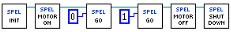
Run the application. The robot motors should turn on, then the robot should move to point 0, then move to point 1, and then the robot motors will turn off.