Remote Monitoring
This function stores data from the robot controller in a cloud database and monitors it remotely via the Internet.
This supports stable robot operation through functions such as anomaly detection and maintenance management.
Preparation
Regarding Robot Controller Settings
- Prepare a PC that can connect to the robot controller via USB.
- Prepare a PC and install Epson RC+ 8.0. Any edition can be used.
Robot Controller Settings
Start RC+ and connect the PC and robot controller via USB. Then select [USB] from the [Connection Status] drop-down list.
Select [System Configuration] from the [Setup] menu.
On the left side of the screen, select [Controller] - [Configure], and configure the following items.
Item Description Example Name Enter any string. Factory-01_Cell-02 IP Address Check the network settings and enter a unique IP address. 192.168.0.50 IP Mask Check the network settings and enter the applicable address. 255.255.255.0 IP Gateway Check the network settings and enter the applicable address. 192.168.0.1 Control Device Select PC/TP4 or Remote I/O. If Remote I/O is not used, set this to PC/TP4. PC/TP4 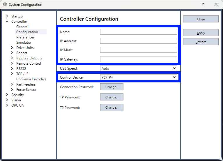
Select [Controller] - [Preferences], and configure the following items.
Item Description Example Enable robot maintenance data Select the checkbox. ✓ 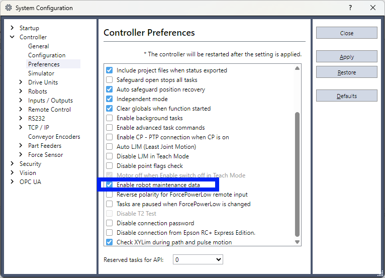
Select [Controller] - [Remote] - [Ethernet], and configure the following items.
Item Description Example TCP/IP Port Number The default value of 5000 is generally acceptable. Change this value if the network to which the controller is connected has port restrictions. 5000 Terminator The default value of CRLF is generally acceptable. CRLF Timeout (seconds) The default value of 60 seconds is generally acceptable. 60 Password Configure as necessary. - Use for Status Monitor Select the checkbox. This setting enables data to be retrieved from the controller. ✓ 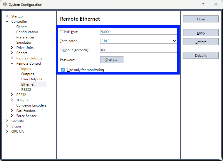
Select [Controller] - [Robot] - [Robot**] - [Configure], and configure the following items.
Item Description Example Name Enter any string. Factory-01_Cell-02_Robot-AA Robot Serial Enter any string. SN_AA 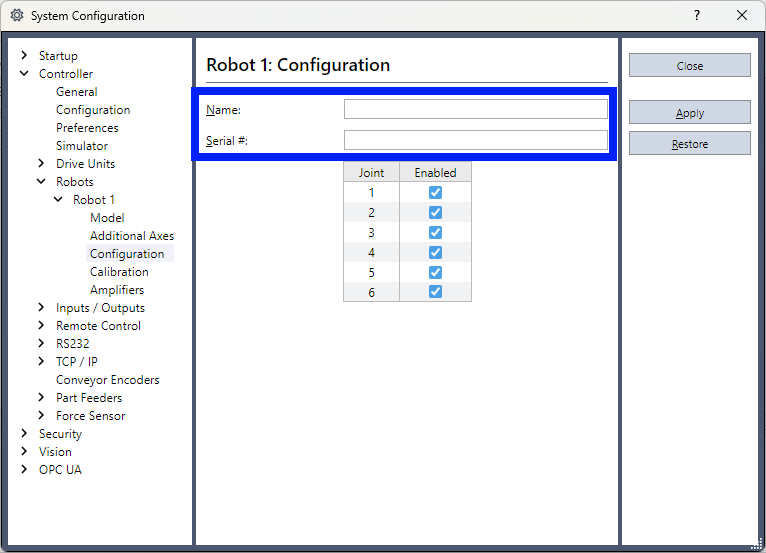
After applying the settings above, close the [System Configuration] screen.
Select [Offline] from the [Connection Status] drop-down list. You can disconnect the USB cable from the PC and robot controller.
Alert Settings
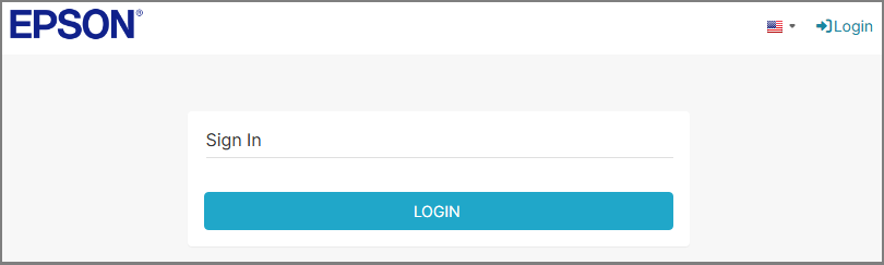
Log in to the Dashboard.
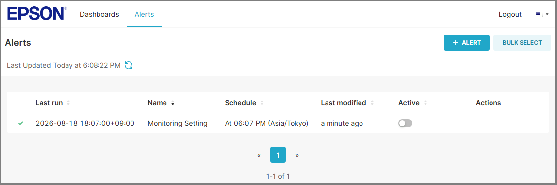
Select the [Alerts] tab to go to the alert list screen, and then select the [+ Alert] button.
Select [General information], and configure the following items.
Item Required Description Example Alert name 〇 Enter any string. Monitoring overload rate Description Configure as necessary. Monitors the overload rate of each robot axis. Email language 〇 Specify the language used in the emails sent. Japanese Alert is active 〇 To start monitoring, set the toggle to ON. ON (set the toggle to the right) 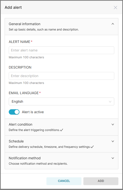
Select [Alert condition], and configure the following items.
Item Required Description Example Alert type 〇 Select any item from the drop-down list. Exceeds threshold Target data 〇 Select any item from the drop-down list. No selection is required if "Error occurred" or "Warning occurred" is selected for [Alert type]. Robot Metric 〇 Select any item from the drop-down list. No selection is required if "Error occurred" or "Warning occurred" is selected for [Alert type]. Overload Rate [%] Threshold 〇 Enter the threshold for the metric according to the alert type. This sets the range of values that triggers a notification. The allowable input range is -999999.000 to 999999.000. 80 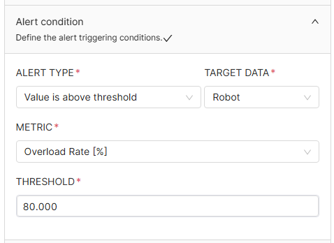
Select [Schedule], and configure the following items.
Item Required Description Example Schedule 〇 Specify the date and time when the alert evaluation is performed. "Every day" evaluates data collected during the 24-hour period preceding the specified schedule. Also, for "Every hour", the evaluation period is the one-hour period preceding the schedule. Every hour at 15 minute Timezone 〇 Specify the timezone for the date and time specified in [Schedule]. (UTC+09:00) Osaka, Sapporo, Tokyo 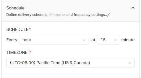
Select [Email Settings], and configure the following items.
Item Required Description Example Email subject name Enter any string. High overload rate detected Email recipients 〇 Enter the notification email address. Separate multiple entries with a comma (,) or semicolon (;). A maximum of five entries can be entered. facility.engineer01@example.com,facility.engineer02@example.com CC recipients 〇 Configure as necessary. To enter an address, select [Add CC recipient], and then enter the notification email address. Separate multiple entries with a comma (,) or semicolon (;). A maximum of five entries can be entered. maintenance.lead@example.com BCC recipients 〇 Configure as necessary. To enter an address, select [Add BCC recipient], and then enter the notification email address. Separate multiple entries with a comma (,) or semicolon (;). A maximum of five entries can be entered. operations@example.com 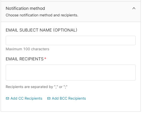
After configuring the settings above, select the [Add] button.
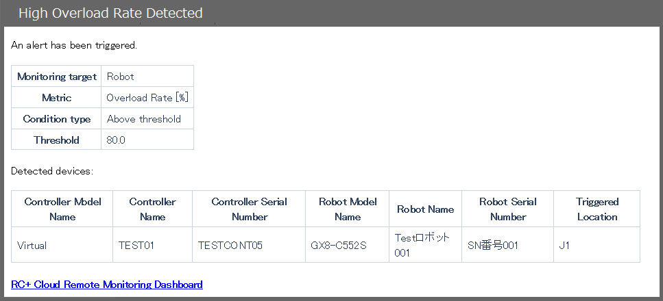
When an alert is detected, an email containing the following information is sent. The email lists multiple devices and includes a link to the Dashboard.
Alert conditions
Item Description Example Target data Displayed according to the configured alert conditions. Robot Metric Displayed according to the configured alert conditions. Overload rate [%] Alert type Displayed according to the configured alert conditions. Exceeds threshold Threshold Displayed according to the configured alert conditions. 80 List of detected devices
Item Description Example Controller Model Name The controller model name is displayed. RC700-A Controller Name Displayed according to the controller settings. Factory-01_Cell-02 Controller Serial Number The controller serial number is displayed. SN12345678 Robot Model Name The robot model name is displayed. C4-A901S Robot name Displayed according to the robot settings. Factory-01_Cell-02_Robot-AA Robot Serial Number Displayed according to the robot settings. SN_AA Triggered Location If the metric is "Overload Rate [%]", the axis number of the detected robot is displayed. If the metric relates to consumables, the detected axis number and part are displayed. J1, J3
Battery/J2: Reduction Gear/J3: Belt, Motor
Operating Procedure
For the operating procedure, refer to the video below. (Playback starts at the relevant section.)