Property setting guidelines for the PressMove object
Step 1. Set basic information
Set properties (Name, Description, Enabled, StepID, AbortSeqOnFail) related to the basic information.
Properties | Description, setting guide |
|---|---|
| Name | This property sets names of force guide objects. Set a particular name. |
| Description | This property sets descriptions about force guide objects. Describe the operations. Set a character string. |
| Enabled | Set whether to execute the force guide object. |
| True : Normal | |
| False : When you do not execute the force guide object (e.g., when you execute another force guide object instead). | |
| StepID | StepID during the force guide object execution. Set an ID. StepID is an ID which is recorded in the log data. It helps you to understand which log data support a process. It is applied when AutoStepID of the force guide sequence is False. |
| AbortSeqOnFail | Set whether to abort or continue the force guide sequence when the force guide object fails. |
True : Normal End a force guide sequence. | |
| False : Cases where the force guide sequence contains recovery operations in case of failure; cases where the sequence will be able to continue even in the event of a failure. |
Step 2. Set I/O processing before starting
Set properties (IOPreprocEnabled, IOPreprocOutputBit, IOPreprocOutputStatus) related to I/O processing before starting force guide object.
Properties | Description, setting guide |
|---|---|
| IOPreprocEnabled | Set whether to operate the output bit when starting the force guide object. You can operate only one output bit. To operate several output bit, use SPELFunc object. |
| False : Normal | |
| True : You operate the output bit, as when you use or stop a peripheral device. | |
| IOPreprocOutputBit | Set the output bit which is operated when the force guide object starts. |
| IOPreprocOutputStatus | Set whether to turn the output bit ON or OFF when the force guide object starts. Set the state to be output. |
Step 3. Set a movement motion
Set properties (MotionTrajectory, AccelS, AccelR, SpeedS, SpeedR, CPEnabled) related to movements.
Properties | Description, setting guide |
|---|---|
| MotionTrajectory | Set types of trajectory to move. |
| Straight : Operates in a straight motion | |
| Arc : Operates in an arcing motion | |
| MultiStraight : Operates multiple points successively in a straight motion | |
| MultiStraightCP : Operates multiple points continuously in a straight motion while linking the trajectory | |
AccelS AccelR | Set an acceleration of the movement. AccelS: Translational Acceleration AccelR: Rotational rotation acceleration Actual acceleration is adjusted by the force control functions. |
SpeedS SpeedR | Set the translational velocity of the movement. SpeedS: Translational Speed SpeedR: Rotational rotation speed Actual speed is adjusted by the force control functions. |
| SpeedRPriority | Sets whether the SpeedR property is prioritized when moving. When the orientation change between points is large relative to the moving distance, operating with the SpeedS property may result in acceleration errors. AutoDistOrientRatio automatically determines whether to use the SpeedR property based on the moving distance between points and the orientation change. Selecting AutoDistOrientRatio is recommended. Select Disabled or Enabled to fix to the SpeedS or SPeedR property. Disabled: When constantly using the SpeedS property Enabled: When constantly using the SpeedR property |
| CPEnabled | Sets whether to connect the trajectory of the PressMove object with that of the following force guide object with Path Motion. True : When operating the robot using multiple PressMove objects while connecting their complex trajectories. |
Step 4. Set a destination point
Set properties (DestType, DestPoint, MidPoint, RelativeOrient, RelativeRobotLocal, DestRelativeX, …, DestRelativeW, MidRelativeX, …, MidRelativeW) related to trajectories to move.
Properties | Description, setting guide |
|---|---|
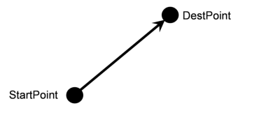
| DestType | This property can set how to set a destination point. If you use the force control functions, the robot positions are adjusted by the force. Therefore, we recommend specifying a destination point by a relative movement amount from the positioning point. RobotPoint : When moving to the specified point Relative : When specifying the relative movement amount |
| DestPoint | Set a point indicating a destination point (DestPoint). When selecting Straight in MotionTrajectory: As shown below, the robot moves in a straight line from the StartPoint of the force guide object to the DestPoint.
|
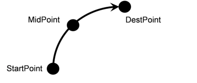
| MidPoint | When the MotionTrajectory is Arc, set a point indicating a middle point (MidPoint). As shown below, the robot moves to the DestPoint after passing through the MidPoint.
|
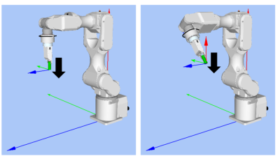
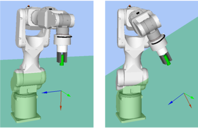
| RelativeOrient | Set a coordinate system direction which will be a reference of the relative movement. |
When specifying Base or Local: As viewed from outside, the robot always operates to a defined direction. The following is an example to set Base. When moving to -Z direction, the robot always moves to the vertical-downward (-Z direction in Base coordinate system) even the orientation of end effector changed. (Black arrow is a direction of the robot motion.) If you want to move the robot in a different direction from the Base coordinate system, specify it using the Local coordinate system.
| |
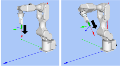
When specifying Tool: Movement direction changes along with the orientation at the start. The following is an example to set Tool. When moving to +Z direction, the moving direction changes depending on the orientation of end effector at the start.
| |
Base, Local: To move the robot to a defined direction as viewed from outside even the robot orientation at the start of the force guide object is changed. | |
Tool: To move to the direction depending on the robot orientation. | |
| RelativeRobotLocal | Set a Local coordinate system number which is used when specifying Local by RelativeOrient. |
DestRelativeX DestRelativeY DestRelativeZ DestRelativeU DestRelativeV DestRelativeW | Set a relative movement amount to each direction from the StartPoint of the force guide object to the DestPoint. As shown below, set a movement amount in the coordinate system specified by RelativeOrient.
|
MidRelativeX MidRelativeY MidRelativeZ MidRelativeU MidRelativeV MidRelativeW | Set a relative movement amount to each direction from the StartPoint of the force guide object to the MidPoint. As shown below, set a movement amount in the coordinate system specified by RelativeOrient.
|
StartPoint EndPoint | This property sets descriptions of force guide objects. As shown in the figure below, when P1 is set for StartPoint and P3 is set for EndPoint, those will be moved continuously in the order of P1, P2, P3.
|


Step 5. Set force control functions
Set properties (Fx_ControlMode, …, Tz_ControlMode, Fx_PressForce, …, Tz_PressForce, Fx_Firmness, …, Tz_Firmness, CFEnabled) related to the force control function.
Properties | Description, setting guide |
|---|---|
Fx_ControlMode Fy_ControlMode Fz_ControlMode Tx_ControlMode Ty_ControlMode Tz_ControlMode | Mode of the force control functions to each direction. Press+: The robot moves to a positive direction of each axis and presses. Press : The robot moves in a negative direction on each axis and presses. When specifying Follow: Perform the follow motion by the force control functions. When specifying Disabled: Force control functions are disabled. Set the ControlMode in pressing direction to Press+ or Press-. Set ControlMode where you want to follow to Follow. One or more directions must be set to a status other than Disabled. |
Fx_PressForce Fy_PressForce Fz_PressForce Tx_PressForce Ty_PressForce Tz_PressForce | Set the force and torque set to each direction. It is used when ControlMode is Press+ or Press- When ControlMode is Press+: Set a negative value. When ControlMode is Press-: Set a positive value. For fittings or assembly tasts, the force is usually set from 3 to 5[N] or from -3 to -5[N] in Fx, Fy, and Fz. However, a proper value differs depending on tasks or workpiece. |
Fx_Firmness Fy_Firmness Fz_Firmness Tx_Firmness Ty_Firmness Tz_Firmness | Set a firmness of the force control functions to each direction. When setting a large value: The Force Control functions become stronger, but response to changes in force is slow. When setting a small value: The Force Control function will become weaker. Response to changes in force is fast; however, vibrations can easily occur. |
| CFEnabled | Set whether to continue the force control functions to the next force guide object. False : Normal Turn OFF the force control functions once, then execute the next force guide object. True : When you want to start the next force guide object, and keep the force constant after contact with the prior object. |
You can check the settings of ControlMode by a simulator.
A coordinate system with grayed out except the enabled direction is displayed. However, the robot is displayed based on the current position. When you check the settings, make sure to move the robot to the position where executing the force guide object.
For details on how to check by using simulator, refer to the following manual.
"Epson RC+ 8.0 User's Guide: - Simulator - Description of Functions"
Step 6. Set basic information for end conditions
Set a property (EndCheckOperator) related to combinations of end conditions.
Properties | Description, setting guide |
|---|---|
| EndCheckOperator | This property sets how to combine the end conditions related to force, position, and I/O. |
| AND : End when all conditions to be used are satisfied. | |
| OR: End when one or more conditions is satisfied. |
Step 7. Set end conditions related to force
Set properties (ForceCheckEnabled, ForceCheckMode, ForceCheckPolarity, PressCheckTolF, PressCheckTolT, FollowCheckTolF, FollowCheckTolT, HoldTimeThresh) related to the end conditions of force.
Properties | Description, setting guide |
|---|---|
| ForceCheckEnabled | This property sets whether to enable the end conditions of force. True : When enabling the end conditions related to force. |
| ForceCheckMode | Target direction of determination. |
Press : Only the pressing direction is evaluated. Directions (Press+, Press-) specified by ControlMode are evaluated. | |
PressFollow : The pressing direction and follow direction are evaluated. Directions (Press+, Press-, Follow) specified by ControlMode are evaluated. | |
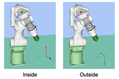
| ForceCheckPolarity | Polar of the end conditions related to force. |
Inside : Normally set. Being inside of the specified range is an end condition. | |
Outside : Being outside of the specified range is an end condition. Use Outside when using a special end condition such as starting with the pressing state and making it as an end condition that the pressing state is released. | |
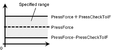
PressCheckTolF PressCheckTolT | This property sets the pressing direction range of the end conditions related to force. Set a range of the end conditions. PressCheckTolF is applied for Fx, Fy, and Fz. PressCheckTolT is applied for Tx, Ty, and Tz. It monitors that the force of directions (Press+, Press-) specified by ControlMode of Fx, Fy, and Fz are within the range of PressForce -PressCheckTolF to PressForce +PressCheckTolF. It monitors that the torque of the force directions (Press+, Press-) specified by ControlMode of Tx, Ty, and Tz is within the range of PressForce -PressCheckTolT to PressForce +PressCheckTolT. The following is an image of PressCheckTolF.
|
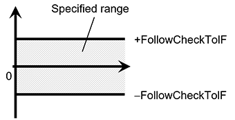
FollowCheckTolF FollowCheckTolT | This property sets the range in the follow direction of the end conditions related to force. FollowCheckTolF is applied for Fx, Fy, and Fz, FollowCheckTolT is applied for Tx, Ty, and Tz It monitors that the force of directions specified to Follow by ControlMode of Fx, Fy, and Fz are within the range of-FollowCheckTolF to +FollowCheckTolF. It monitors that the torque of directions specified to Follow by ControlMode of Tx, Ty, and Tz are within the range of -FollowCheckTolT to +FollowCheckTolT. The following is an image of InsertCheckTolF.
|
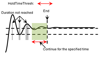
| HoldTimeThresh | Set the duration time which is used to determine whether the end conditions have satisfied. As shown below, if the specified condition continues for the time specified by HoldTimeThresh, it is determined as the end conditions are satisfied.
Normally, set to "0". Set the time for stabilizing the motion when the results of the next force guide object are unstable. We recommend setting the time according to the actual result which is executed after temporarily disabling the end conditions. |
Step 8. Set end conditions about position
Set properties (PosCheckEnabled, PosCheckType, PlaneNumber, PlaneEndCond, PlaneRelativeOrg, PlaneRelativeX, PlaneRelativeY, PlaneRelativeZ, PlaneRelativeOrient, PlaneAxes, PlaneRelativeRobotLocal) related to the end conditions of the positions.
Properties | Description, setting guide |
|---|---|
| PosCheckEnabled | This property sets whether to enable the end conditions of positions. |
| True : When the end conditions related to position are enabled. | |
| False : When the end conditions related to position are disabled. | |
| PosCheckType | Select types of the end conditions related to positions. |
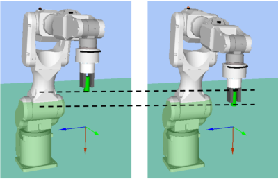
When selecting RobotPlane: End conditions are based on the set Plane. As shown below, use this property for setting the end conditions based on a defined position regardless of the position of the robot.
| |
When selecting RelativePlane: Every time the force guide sequence is executed, create Plane at a relative position from the current position and set as an end condition of position. As shown below, use this property for changing the end condition positions depending on the position at the start.
| |
| PlaneNumber | Set Plane number which is used for an end condition of positions. |
When PosCheckType is RobotPlane: End conditions based on the specified Plane number are set. | |
When PosCheckType is RelativePlane: Every time the force guide sequence is executed, set Plane to the specified number. Set an empty Plane number. | |
| PlaneEndCond | Set the state of the end condition of positions. Set either Inside (inside the Plane) or Outside (outside of the Plane) as an end condition. When the robot will be the specified state, it is determined as the end conditions of the positions are satisfied. Inside the plane: It is in +Z direction of Plane.
|
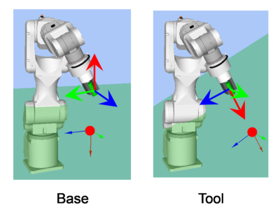
| PlaneRelativeOrg | Set which coordinate system direction is used as a reference when expressing the offset amount to the origin of Plane. The left figure below is an example to set Base. Specify a relative distance based on the Base coordinate system. It is an example that the negative value is set in PlaneRelativeZ. The right figure below is an example to set Tool. Specify a relative distance based on the Tool coordinate system. It is an example that the positive value is set in PlaneRelativeZ.
The Local or Tool coordinate systems are used only in that direction and origin position does not affect. To set the position of an end condition in the robot motion direction, normally set the same value as ForceOrient of the force guide sequence. |
PlaneRelativeX PlaneRelativeY PlaneRelativeZ | Set offset amount in each direction from the current position to the origin of Plane. Direction will be the coordinate system direction specified by PlaneRelativeOrg. |
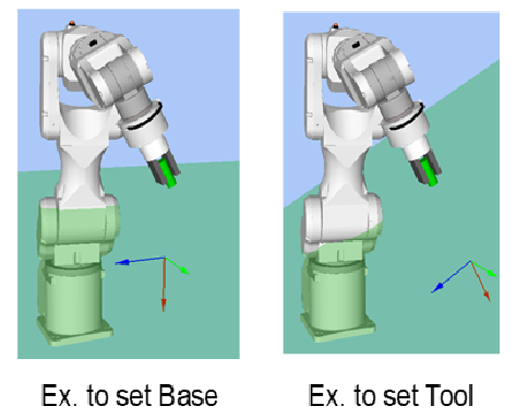
| PlaneRelativeOrient | Set a coordinate system based on the Plane direction. The left figure below is an example to set Base. Reference direction of the Plane matches the Base coordinate system regardless of the robot orientation at the start of the force guide object. The right figure below is an example to set Tool. Reference direction of the Plane changes along with the robot orientation at the start of the force guide object.
Since a plane which is perpendicular to the robot motion direction will be the end conditions, normally set the same value as ForceOrient of the force guide sequence. |
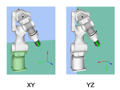
| PlaneAxes | Set a Plane direction Based on the coordinate system specified by PlaneRelativeOrient, plane is set to a direction set by PlaneAxes. The following figure is an example when Base is set by PlaneRelativeOrient. Left figure: XY is specified by PlaneAxes. Right figure: YZ is specified by PlaneAxes.
Normally, set Plane which is perpendicular to the robot motion direction. |
| PlaneRelativeRobotLocal | Set Local coordinate system number which is used when PlaneRelativeOrg and PlaneRelativeOrient are Local. Normally, set a value which is the same as RobotLocal of the force guide sequence. |
Step 9. Set end conditions related to I/O
Set properties (IOCheckEnabled, IOCheckInputBit, IOCheckInputStatus) related to the end conditions of I/O.
Properties | Description, setting guide |
|---|---|
| IOCheckEnabled | This property sets whether to enable the end conditions of I/O. True : When the end conditions related to I/O are enabled. |
| IOCheckInputBit | Set an input bit which is monitored as an end condition. |
| IOCheckInputStatus | Set a state of the input bit to be an end condition. If the input bit specified by IOCheckInputBit will be the state specified by IOCheckInputStatus, it is determined as the end conditions are satisfied. |