Each error code has Notes to show details of the error, and some Notes have the complex information need the explanation.
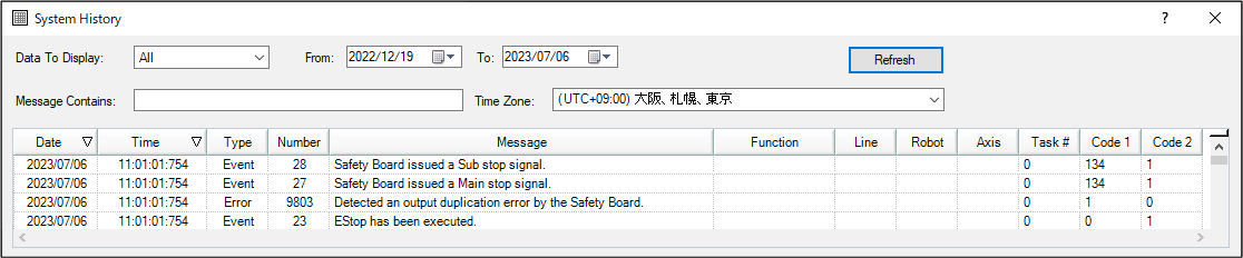
You can check each error code's Note from the system history of Epson RC+.
Error Code 27, 28: "Safety Board issued a Main stop signal." and "Safety Board issued a Sub stop signal."
The Note for the error message "Safety Board issued a Main stop signal" and "Safety Board issued a Sub stop signal" describe the reason for stoppage by the Safety Function.
Note 1: Type of Stop Signal
Note 2: Details of stop signal (meaning differs according to Note 1: Type of stop signal)
As the safety functions are monitored by independent redundant circuits, errors with the same Note information may be reported multiple times with error codes 27 (main) and 28 (sub).
The type of safety board stop signal and the current values of the details can also be obtained with the SF_GetStatus function. For more information, refer to the following manual:
Epson RC+ 8.0 SPEL+ Language Reference
For more information about terminology related to the safety functions, refer to the following manual:
Safety Function Manual
| Note Information | Overview and Countermeasure | |||
|---|---|---|---|---|
| Note 1 (*1) | Note 2 | |||
| No. | Type of Stop Signal | Details of Stop Signal | ||
| 100 | Safety Input | No. | Safety Input Port | Stopped due to an emergency stop or safeguard assigned to the Note 2 safety input. Turn on the NC contact (normally closed contact) of the safety switch connected to the safety input port notified in Note 2. (*6) |
| 1 (*4) | SAFETY_IN1 | |||
| 2 (*5) | SAFETY_IN2 | |||
| 4 | SAFETY_IN3 | |||
| 8 | SAFETY_IN4 | |||
| 16 | SAFETY_IN5 | |||
| 101 | Safety Limited Speed for joint of robot (SLS_1) | No. | Joint No. | The robot stopped because the speed of the joint shown in Note 2 exceeded the SLS_1 safety speed. Refer to "Check Items When Stopped Due to Safety Limited Speed (SLS)" and take the appropriate countermeasures. |
| 1 | J1 | |||
| 2 | J2 | |||
| 4 | J3 | |||
| 8 | J4 | |||
| 16 | J5 | |||
| 32 | J6 | |||
| 102 | Safety Limited Speed for part of robot (SLS_1) | No. | Part | The robot stopped because the speed of the part shown in Note 2 exceeded the SLS_1 safety speed. Refer to "Check Items When Stopped Due to Safety Limited Speed (SLS)" and take the appropriate countermeasures. |
| 1 | Tip (P1 TCP) | |||
| 2 | Elbow (P2 Elbow) | |||
| 4 | Wrist (P3 Wrist) | |||
| 8 | Shoulder (P4 Shoulder) | |||
| 103 | Safety Limited Speed for joint of robot (SLS_2) | No. | Joint No. | The robot stopped because the speed of the joint shown in Note 2 exceeded the SLS_2 safety speed. Refer to "Check Items When Stopped Due to Safety Limited Speed (SLS)" and take the appropriate countermeasures. |
| 1 | J1 | |||
| 2 | J2 | |||
| 4 | J3 | |||
| 8 | J4 | |||
| 16 | J5 | |||
| 32 | J6 | |||
| 104 | Safety Limited Speed for part of robot (SLS_2) | No. | Part | The robot stopped because the speed of the part shown in Note 2 exceeded the SLS_2 safety speed. Refer to "Check Items When Stopped Due to Safety Limited Speed (SLS)" and take the appropriate countermeasures. |
| 1 | Tip (P1 TCP) | |||
| 2 | Elbow (P2 Elbow) | |||
| 4 | Wrist (P3 Wrist) | |||
| 8 | Shoulder (P4 Shoulder) | |||
| 105 | Safety Limited Speed for joint of robot (SLS_3) | No. | Joint No. | The robot stopped because the speed of the joint shown in Note 2 exceeded the SLS_3 safety speed. Refer to "Check Items When Stopped Due to Safety Limited Speed (SLS)" and take the appropriate countermeasures. |
| 1 | J1 | |||
| 2 | J2 | |||
| 4 | J3 | |||
| 8 | J4 | |||
| 16 | J5 | |||
| 32 | J6 | |||
| 106 | Safety Limited Speed for part of robot (SLS_3) | No. | Part | The robot stopped because the speed of the part shown in Note 2 exceeded the SLS_3 safety speed. Refer to "Check Items When Stopped Due to Safety Limited Speed (SLS)" and take the appropriate countermeasures. |
| 1 | Tip (P1 TCP) | |||
| 2 | Elbow (P2 Elbow) | |||
| 4 | Wrist (P3 Wrist) | |||
| 8 | Shoulder (P4 Shoulder) | |||
| 107 | Safety Limited Speed for joint of robot (SLS_T) | No. | Joint No. | The robot stopped because the speed of the joint shown in Note 2 exceeded the SLS_T safety speed in TEACH mode. Drop the robot operating speed or check the safety parameters related to SLS_T set in the Safety Function Manager. |
| 1 | J1 | |||
| 2 | J2 | |||
| 4 | J3 | |||
| 8 | J4 | |||
| 16 | J5 | |||
| 32 | J6 | |||
| 108 | Safety Limited Speed for part of robot (SLS_T) | No. | Part | The robot stopped because the speed of the part shown in Note 2 exceeded the SLS_T safety speed in TEACH mode. Drop the robot operating speed or check the safety parameters related to SLS_T set in the Safety Function Manager. |
| 1 | Tip (P1 TCP) | |||
| 2 | Elbow (P2 Elbow) | |||
| 4 | Wrist (P3 Wrist) | |||
| 8 | Shoulder (P4 Shoulder) | |||
| 109 | Safety Limited Speed for joint of robot (SLS_T2) | No. | Joint No. | The robot stopped because the speed of the joint shown in Note 2 exceeded the SLS_T2 safety speed in T2 mode. Drop the robot operating speed or check the safety parameters related to SLS_T2 in the Safety Function Manager. |
| 1 | J1 | |||
| 2 | J2 | |||
| 4 | J3 | |||
| 8 | J4 | |||
| 16 | J5 | |||
| 32 | J6 | |||
| 110 | Safety Limited Speed for part of robot (SLS_T2) | No. | Part | The robot stopped because the speed of the part shown in Note 2 exceeded the SLS_T2 safety speed in T2 mode. Drop the robot operating speed or check the safety parameters related to SLS_T2 in the Safety Function Manager. |
| 1 | Tip (P1 TCP) | |||
| 2 | Elbow (P2 Elbow) | |||
| 4 | Wrist (P3 Wrist) | |||
| 8 | Shoulder (P4 Shoulder) | |||
| 115 | Safety Limited Position (SLP_A) | No. | Joint No., Monitored Position (*2) | The robot stopped because the joint number and joint position shown in Note 2 intruded into the SLP_A monitored position. Refer to "Check Items When Stopped Due to Safety Limited Position (SLP)". Reset or take the appropriate countermeasures. |
| 1001 (*3) | J2, YL | |||
| 2001 (*3) | J2, YU | |||
| 4001 (*3) | J2, XL | |||
| 8001 (*3) | J2, XU | |||
| 16001 (*3) | J2, ZL | |||
| 32001 (*3) | J2, ZU | |||
| 1002 (*3) | J3, YL | |||
| 2002 (*3) | J3, YU | |||
| 4002 (*3) | J3, XL | |||
| 8002 (*3) | J3, XU | |||
| 16002 (*3) | J3, ZL | |||
| 32002 (*3) | J3, ZU | |||
| 1004 (*3) | J5, YL | |||
| 2004 (*3) | J5, YU | |||
| 4004 (*3) | J5, XL | |||
| 8004 (*3) | J5, XU | |||
| 16004 (*3) | J5, ZL | |||
| 32004 (*3) | J5, ZU | |||
| 1008 (*3) | J6, YL | |||
| 2008 (*3) | J6, YU | |||
| 4008 (*3) | J6, XL | |||
| 8008 (*3) | J6, XU | |||
| 16008 (*3) | J6, ZL | |||
| 32008 (*3) | J6, ZU | |||
| 116 | Safety Limited Position (SLP_B) | No. | Joint No., Monitored Position (*2) | The robot stopped because the joint number and joint position shown in Note 2 intruded into the SLP_B monitored position. Refer to "Check Items When Stopped Due to Safety Limited Position (SLP)". Reset or take the appropriate countermeasures. |
| 1001 (*3) | J2, YL | |||
| 2001 (*3) | J2, YU | |||
| 4001 (*3) | J2, XL | |||
| 8001 (*3) | J2, XU | |||
| 16001 (*3) | J2, ZL | |||
| 32001 (*3) | J2, ZU | |||
| 1002 (*3) | J3, YL | |||
| 2002 (*3) | J3, YU | |||
| 4002 (*3) | J3, XL | |||
| 8002 (*3) | J3, XU | |||
| 16002 (*3) | J3, ZL | |||
| 32002 (*3) | J3, ZU | |||
| 1004 (*3) | J5, YL | |||
| 2004 (*3) | J5, YU | |||
| 4004 (*3) | J5, XL | |||
| 8004 (*3) | J5, XU | |||
| 16004 (*3) | J5, ZL | |||
| 32004 (*3) | J5, ZU | |||
| 1008 (*3) | J6, YL | |||
| 2008 (*3) | J6, YU | |||
| 4008 (*3) | J6, XL | |||
| 8008 (*3) | J6, XU | |||
| 16008 (*3) | J6, ZL | |||
| 32008 (*3) | J6, ZU | |||
| 117 | Safety Limited Position (SLP_C) | No. | Joint No., Monitored Position (*2) | The robot stopped because the joint number and joint position shown in Note 2 intruded into the SLP_C monitored position. Refer to "Check Items When Stopped Due to Safety Limited Position (SLP)". Reset or take the appropriate countermeasures. |
| 1001 (*3) | J2, YL | |||
| 2001 (*3) | J2, YU | |||
| 4001 (*3) | J2, XL | |||
| 8001 (*3) | J2, XU | |||
| 16001 (*3) | J2, ZL | |||
| 32001 (*3) | J2, ZU | |||
| 1002 (*3) | J3, YL | |||
| 2002 (*3) | J3, YU | |||
| 4002 (*3) | J3, XL | |||
| 8002 (*3) | J3, XU | |||
| 16002 (*3) | J3, ZL | |||
| 32002 (*3) | J3, ZU | |||
| 1004 (*3) | J5, YL | |||
| 2004 (*3) | J5, YU | |||
| 4004 (*3) | J5, XL | |||
| 8004 (*3) | J5, XU | |||
| 16004 (*3) | J5, ZL | |||
| 32004 (*3) | J5, ZU | |||
| 1008 (*3) | J6, YL | |||
| 2008 (*3) | J6, YU | |||
| 4008 (*3) | J6, XL | |||
| 8008 (*3) | J6, XU | |||
| 16008 (*3) | J6, ZL | |||
| 32008 (*3) | J6, ZU | |||
| 118 | Soft Axis Limiting | No. | Joint No. | The robot stopped because the joint number shown in Note 2 exceeded the joint movement range at the soft axis limit. Refer to "Check Items When Stopped Due to Soft Axis Limiting". Reset or take the appropriate countermeasures. |
| 1 | J1 | |||
| 2 | J2 | |||
| 4 | J3 | |||
| 8 | J4 | |||
| 16 | J5 | |||
| 32 | J6 | |||
121 | Switch Input | No. | Switch No. | This is event information notified by the Safety board in the following cases. No action is required for this notification. (*7) Enable switch: Emergency stop switch 1: These switches are located on the Teach Pendant. Emergency stop switch 2: This switch is connected to the emergency stop input connector of the controller. |
| 1 | Enable switch | |||
| 2 | Emergency stop switch 1 | |||
| 4 | Emergency stop switch 2 | |||
| 122 | Mode Control | No. | State | This is event information that notifies a status change of mode control on the safety board. No action is required for this notification. |
| - | - | |||
| 123 | Deceleration Monitoring | No. | State | This is event information that notifies the status of deceleration monitoring on the safety board. No action is required for this notification. |
| - | - | |||
| 124 | Joint Angle Monitoring | No. | Joint No. | The robot stopped because the joint shown in Note 2 exceeded the joint angle limit during joint angle monitoring. Check the following items. 1. Has an appropriate joint angle limit been set? 2. Was the joint angle monitoring enabled after the robot fully stopped? 3. Was an operation command executed while the joint angle monitoring was disabled? 4. Was the robot subjected to vibrations due to some external factor? |
| 1 | J1 | |||
| 2 | J2 | |||
| 4 | J3 | |||
| 8 | J4 | |||
| 16 | J5 | |||
| 32 | J6 | |||
Other than the above (*1) | Notifies when a safety board error occurred. Refer to (*1). | |||
*1: If Note 1 is not listed in the table, it is event information for when the Safety Board issues an error notification. No action is required for this notification. You are notified of errors related to this event before and after the system history. Handle the errors appropriately.
Example: "Error 9803" is notified if Note 1 is "134."
*2: The correspondence between the monitored positions X1, X2, Y1, Y2, Z1, Z2 for the Safety Limited Position in the Safety Function Manager and the monitored positions XL, XU, YL, YU, ZL, ZU referred to in this manual is as follows:
- "Wall" selected as the monitored position: X1 = XL, X2 = XU, Y1 = YL, Y2 = YU, Z1 = ZL, Z2 = ZU
- "Restricted Area" is selected as the monitored position: X1 = XU, X2 = XL, Y1 = YU, Y2 = YL
For more information, refer to the following manual:
"Robot Controller Safety Function Manual Setting Safety Limited Position (SLP)"
**3: A 4 to 5-digit number string that indicates the joint number and monitored position.
- Lower 3 digits (digit 1 to 3): Joint number (001: J2, 002: J3, 004: J5, 008: J6)
- Next 1 or 2 digit (digit 4 to 5): Monitored position (1: YL, 2: YU, 4: XL, 8: XU, 16: ZL, 32: ZU)
Example: If Note 2 is "1002," a stop signal was issued because joint number J3 (lower 3 digits are 002) exceeded monitored position YL (next 1 digit is 1).
**4: As SAFETY_IN1 is set to Emergency Stop (ESTOP) in the initial controller settings, connect an emergency stop switch. Or change the setting with the Safety Function Manager.
**5: As SAFETY_IN2 is set to Safeguard (SG) in the initial controller settings, connect a safeguard (safety fence with safety switch, etc.). Or change the setting with the Safety Function Manager.
**6: When the robot stops because the emergency stop switch connected to the emergency stop input connector of the controller or the emergency stop switch on the Teach Pendant was pressed, "121" is recorded in Note 1.
**7: When the robot stops because the safety input causes an emergency stop, "100" is recorded in Note 1.