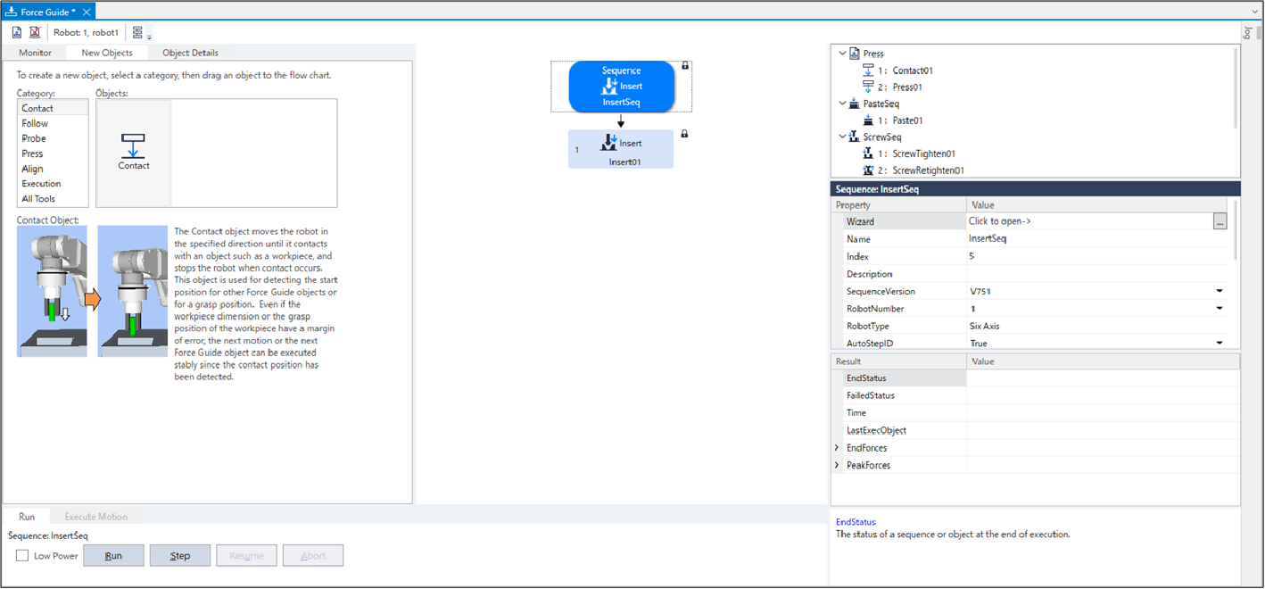
Sequence wizard
The following describes how to create Insert sequence of the system force guide sequences.
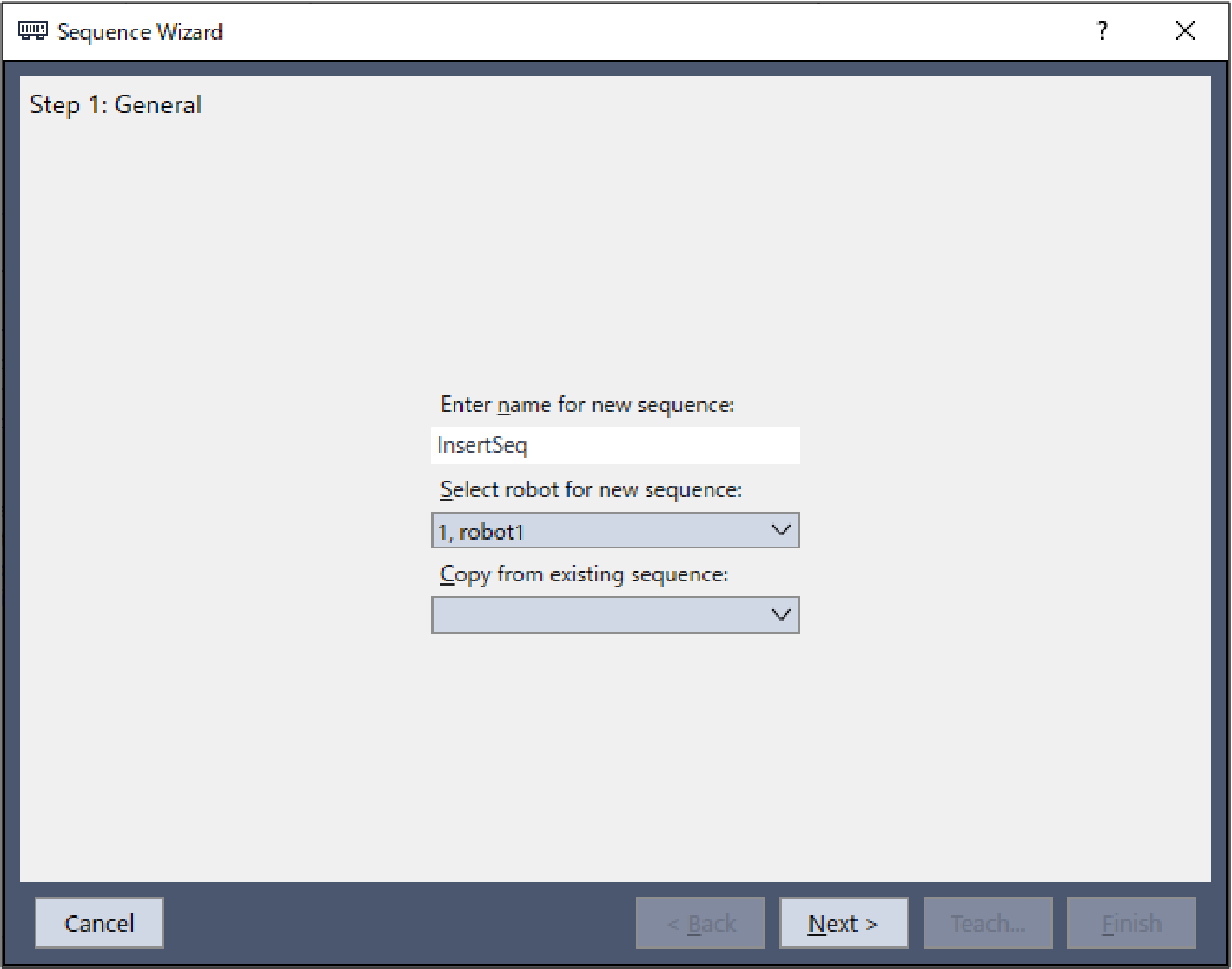
Enter "InsertSeq" in the [Enter name for new sequence] box. Click the [Next] button.
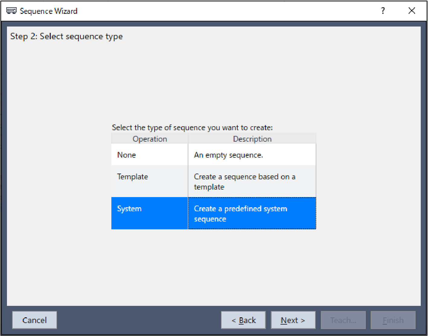
The [Step 2: Select sequence type] dialog box is displayed.
Select [System]. Click the [Next] button.
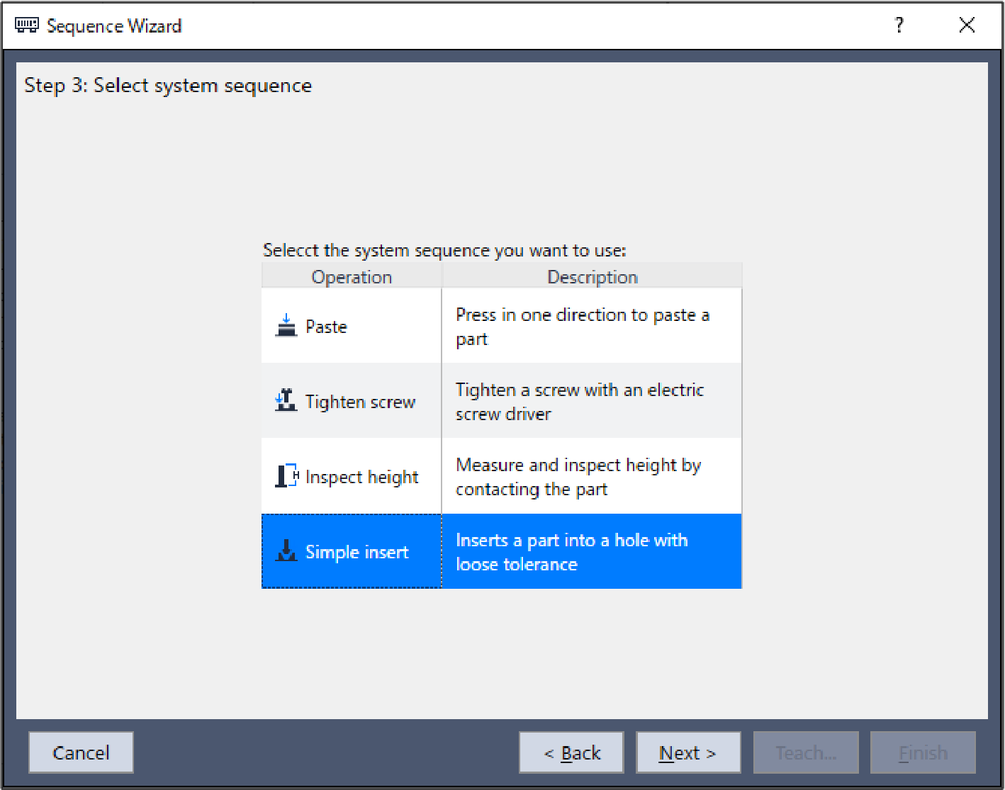
The [Step 3: Select system sequence] dialog box is displayed. Select [Simple insert]. Click the [Next] button.
The [Step 4: Select the robot tool to use for the end effector] dialog box is displayed.
Change the properties according to the table below.
Click the [Next] button.
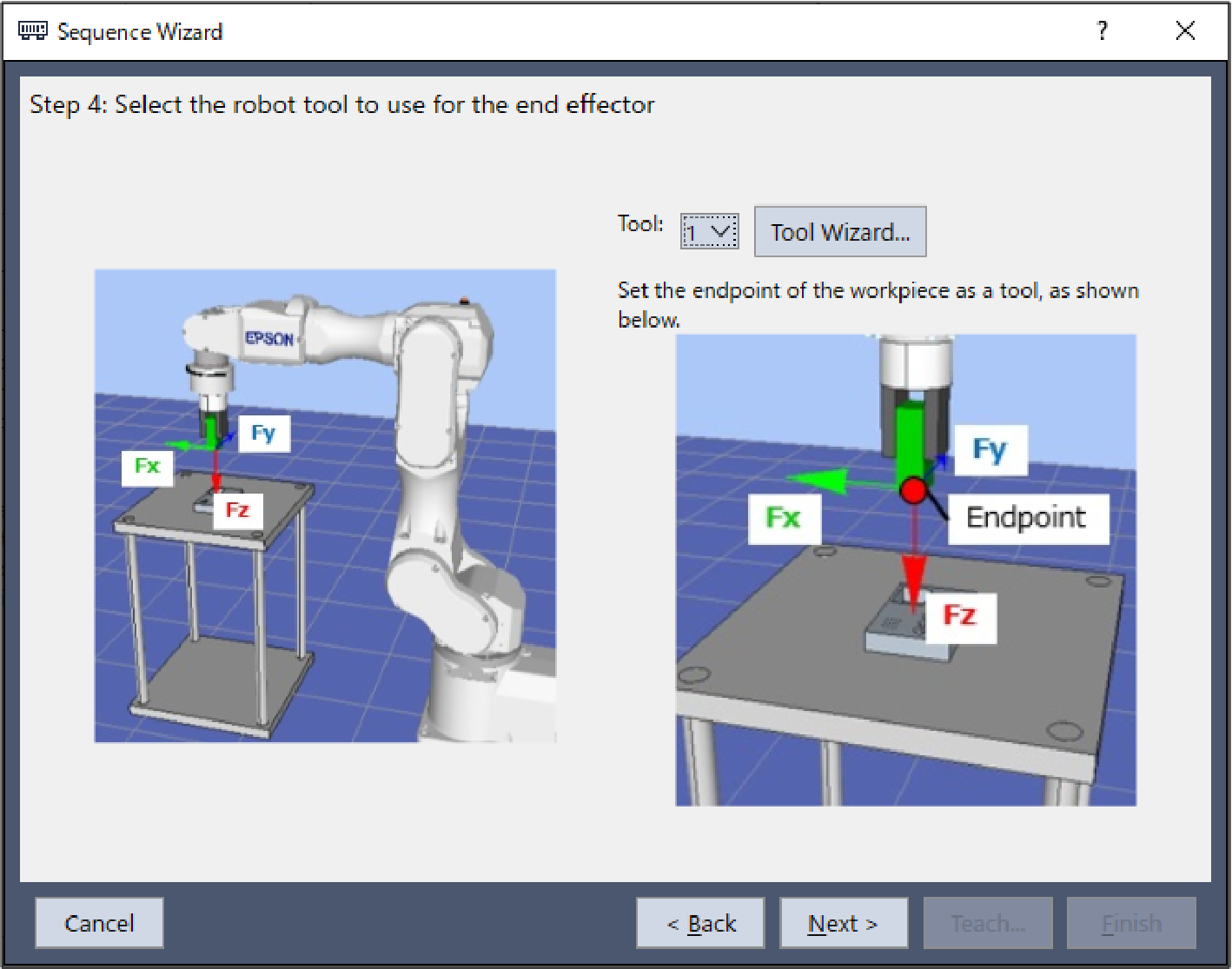 ItemValueDescription
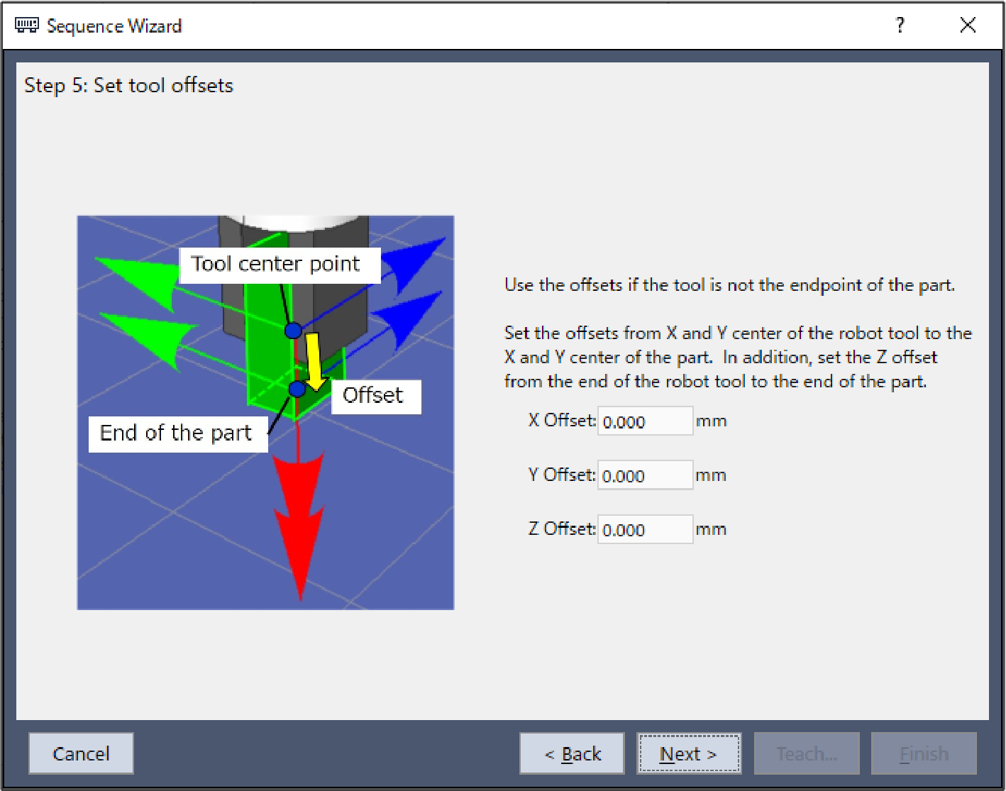
Tool 1 Specify the number set for the tool used in this sequence. The [Step 5: Set tool offsets] dialog box is displayed.
Set tool offset values. These values can be left as the default values and do not need to be changed.
Click the [Next] button.
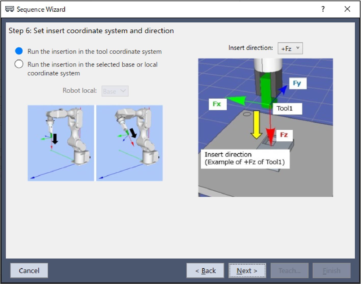
The [Step 6: Set insert coordinate system and direction] dialog box is displayed.
This tutorial performs the insertion to +Fz direction of the tool coordinate system.
(*1) As the coordinate system is set to tool and the insertion direction is set to +Fz, this value can be left as the default value and does not need to be changed.
Click the [Next] button.
*1 [Reference]6-axis robotSCARA robotRobot motion image
[Insert]
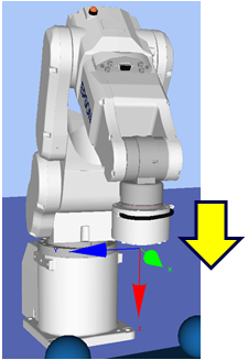
(Press/Contact)
Orient
+Fz -Fz Sign of Force
(monitor display is included)
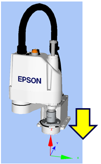
- + The [Step 7: Set insert operation options] dialog box is displayed.
Change the properties according to the table below.
Click the [Next] button.
 ItemValueDescription
Enable insertion alignment Disable The insertion alignment is enabled.
The insertion alignment is not required since this tutorial uses a cylinder as a workpiece.
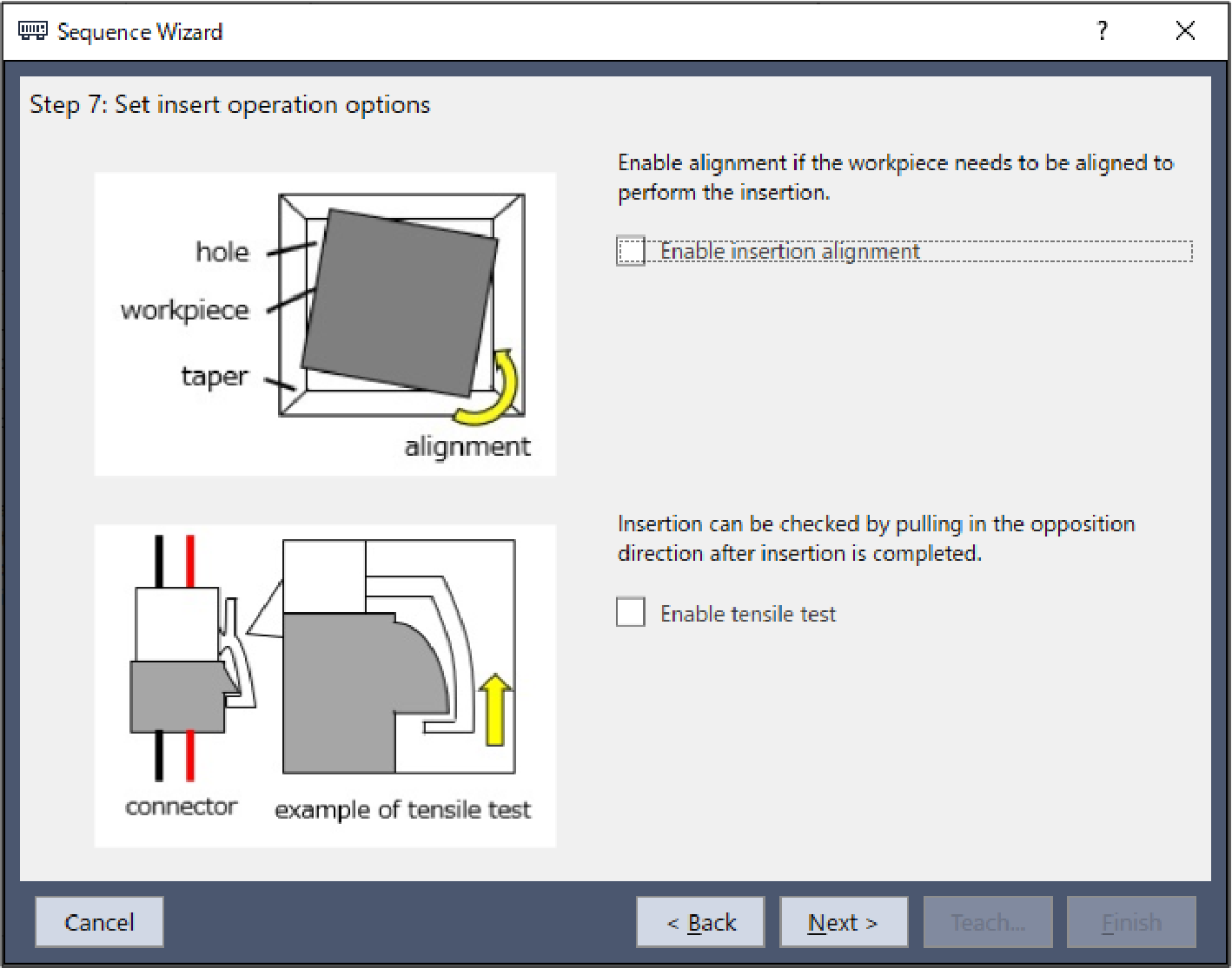
The [Step 8: Set insert approach distance and depth] dialog box is displayed.
Change the properties according to the table below.
Click the [Next] button.
 ItemValueDescription
Approach distance 3 Set the distance from the end of the cylinder to the hole face.
Set this to 3mm.
Insert depth 30 Set the depth of the hole.
Set this to 30mm.
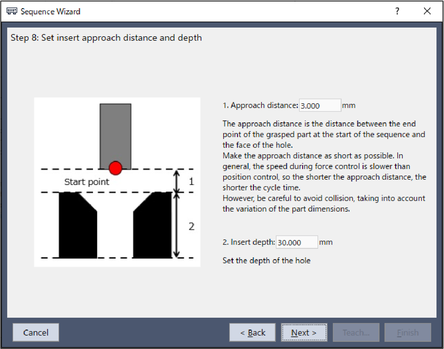
The [Step 9: Set insertion parameters] dialog box is displayed.
Change the properties according to the table below.
Click the [Next] button.
 ItemValueDescription
Tolerance Loose Set the speed and force of insertion based on the tolerance of the cylinder and the hole.
Select this according to the tolerance of the workpiece in use.
When Loose is selected for Tolerance, the insertion speed is 5 mm/sec.
When Loose is selected for Tolerance and Hard for Toughness, the insertion force is -12 N.
Toughness Hard Set the firmness of the force control function for the insertion force and the insertion force based on the firmness of the cylinder and the hole.
Select this according to the material of the workpiece in use.
When selecting Hard for Toughness, the firmness of the force control function in the insertion direction is 1.
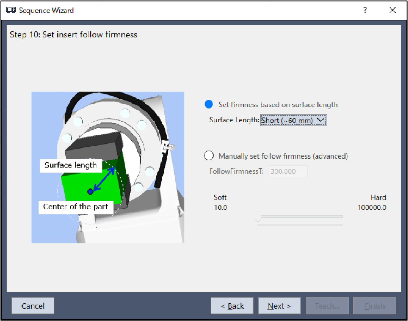
The [Step 10: Set insert follow firmness] dialog box is displayed.
Change the properties according to the table below.
Click the [Next] button.
 ItemValueDescription
Surface Length Short (up to 60 mm) Set the firmness of the force control function in the following direction based on the distance from TCP to the end of the workpiece.
Select this according to the tolerance of the workpiece in use.
When Short (up to 60 mm) is selected for Surface Length, the firmness of the force control function in the follow direction is 300.
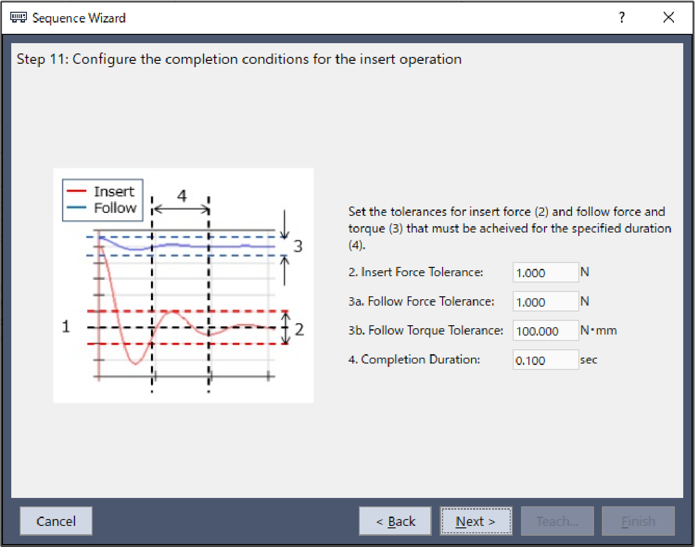
The [Step 11: Configure the completion conditions for the insert operation] dialog box is displayed. When each property setting is changed, the completion conditions of the inserting operation. In this tutorial, the values do not need to be changed from the default values. Click the [Next] button.
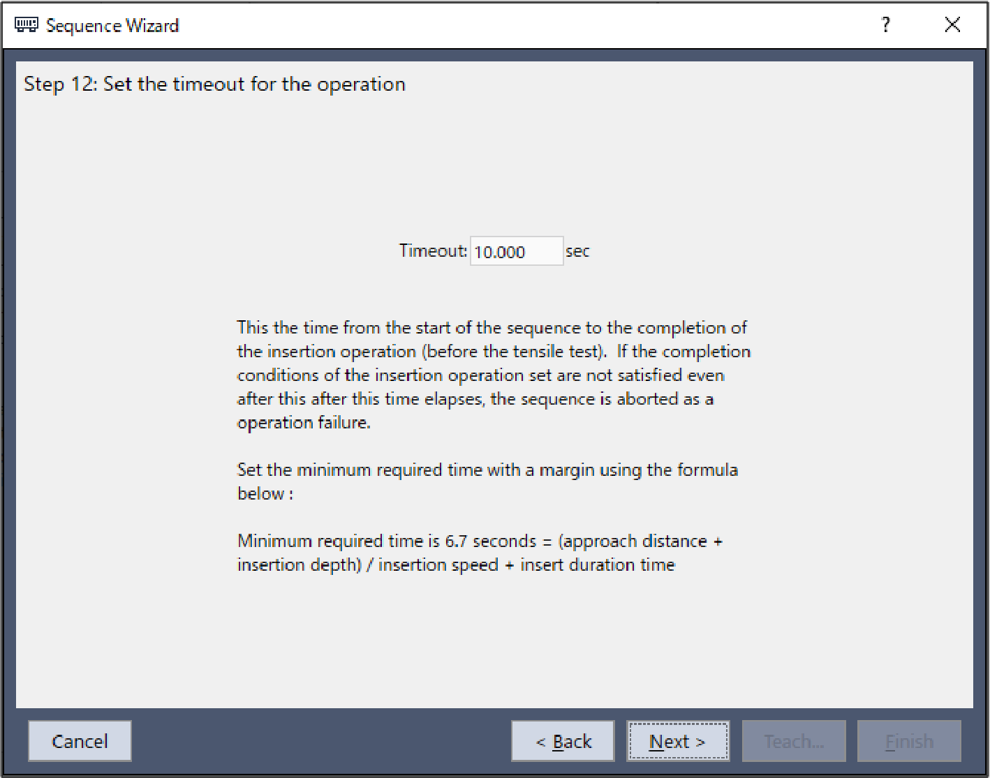
The [Step 12: Set the timeout for the operation] dialog box is displayed. This setting does not need to be changed from its default value. Click the [Next] button.
The [Finish] dialog box is displayed. Click the [Finish] button.
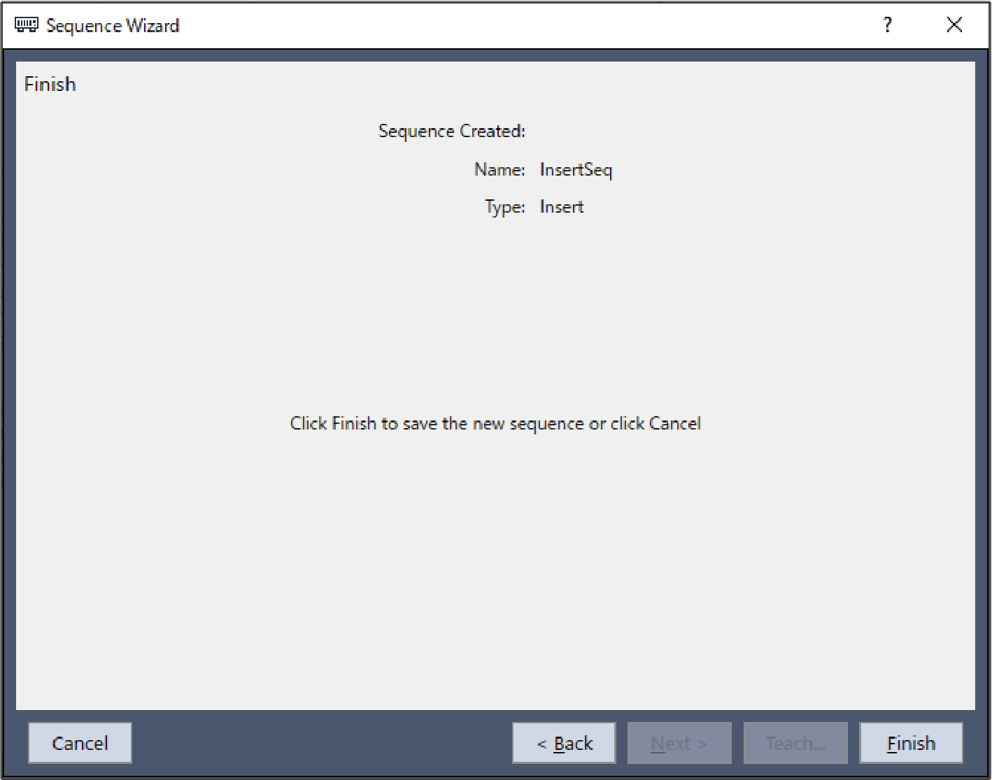
Check that the [InsertSeq] sequence has been created.