Confirmation of Tool Setting
The following describes tool setting procedures.
In the HeightInspect sequence, you need to consider the behavior of the actual inspecting direction and the current tool settings.
Use a caliper to measure the distance from the J6 flange plane to the contact point of the workpiece that is attached when you inspect the height.
Execute the following in [Command Window].
In "Length", enter the value measured in the procedure (1).> Tlset 1,XY(0,0,Length,0,0,0)Click Epson RC+ menu-[Tools]-[Simulator]. The [Simulator] window is displayed.
Select the object tree-[Manipulator Name]-[Tool].
Place a checkmark in "No.1"-[Visible] check box.
To confirm that the tool setting is correct, compare the display of the [Simulator] window and the orientation of the actual robot.
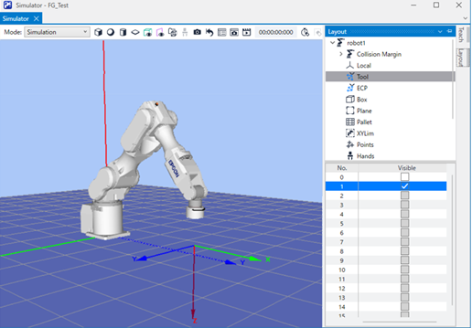
According to the display of the [Simulator] window, you will see that height inspection is performed to +Z direction of the tool.
Position Teaching
The following describes how to teach a sequence start position of HeightInspect sequence.
Click Epson RC+ menu-[Tools]-[Robot Manager].
The [Robot Manager] dialog box appears.Select [Jog & Teach] and open the panel.
Select "1" on [Tool].
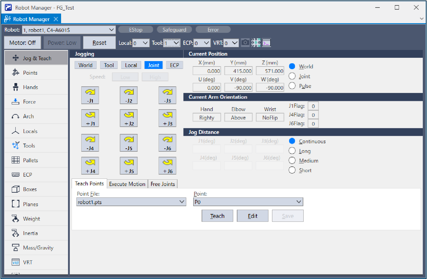
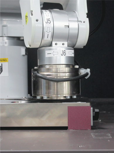
Click the Jog button to move the robot to about 3mm above the contact point with the object to be inspected.
Execute the following command in the command window if necessary.> Go Align(Here)By executing the above command, the robot will be a parallel orientation against the Base coordinate system based on the current position. The robot can move more easily when it and the contact point are facing one another.
For details, refer to the following manual: Epson RC+ SPEL+ Language Reference Align FunctionSelect "P1" in the [Point] dropdown.
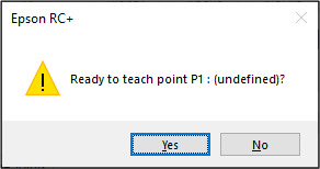
Click the [Teach] button.
The following message is displayed.
Confirm the message and click the [Yes] button.
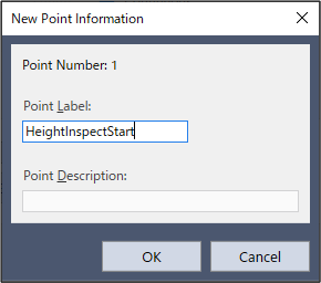
The [New Point Information] dialog box is displayed.
Enter "HeightInspectStart" to [Point Label] and click the [OK] button.
Click Epson RC+ menu-[File]-[Save All].
Set contents will be saved in the file.
Sequence wizard
The following describes how to create HeightInspect sequence of the system force guide sequences.
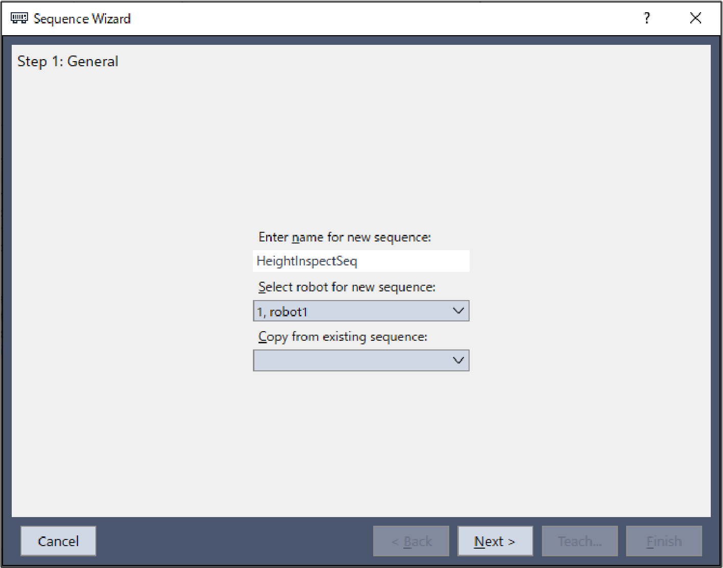
- Enter "HeightInspectSeq" in the [Enter name for new sequence] box.
Click the [Next] button.
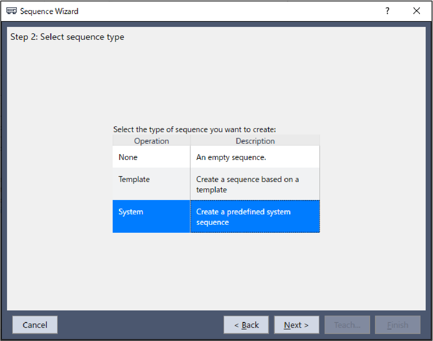
- The [Step 2: Select sequence type] dialog box is displayed.
Select [System]. Click the [Next] button.
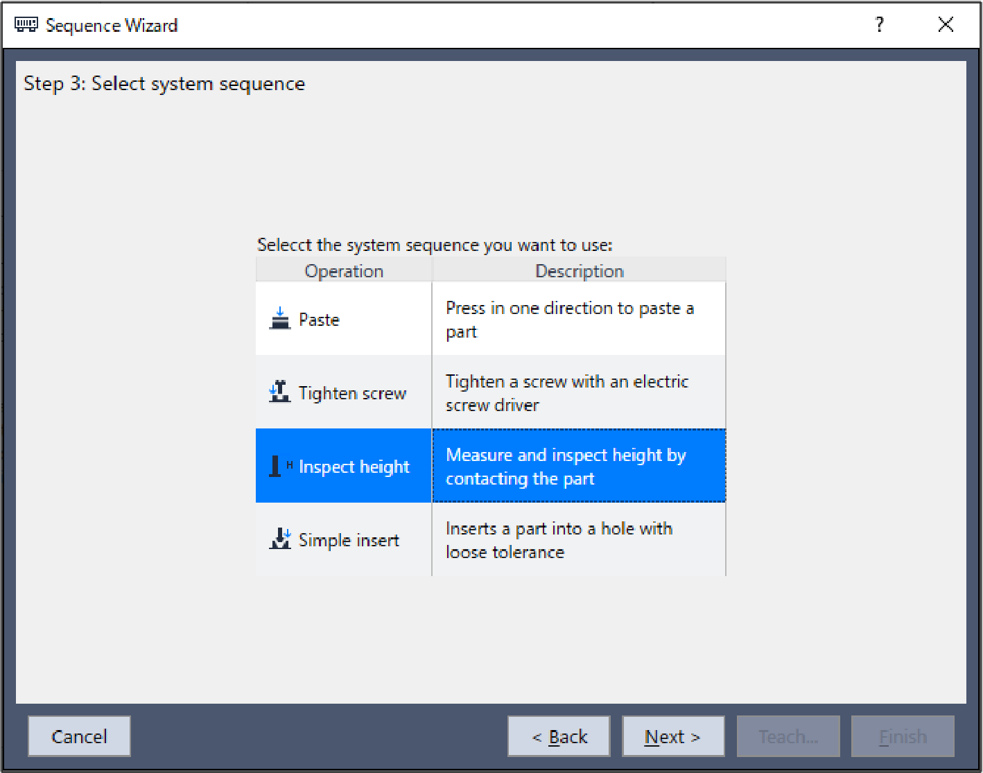
- The [Step 3: Select system sequence] dialog box is displayed.
Select [Inspect height].
Click the [Next] button.
- The [Step 4: Select the robot tool to use for the end effector] dialog box is displayed.
Change the properties according to the table below.
Click the [Next] button.
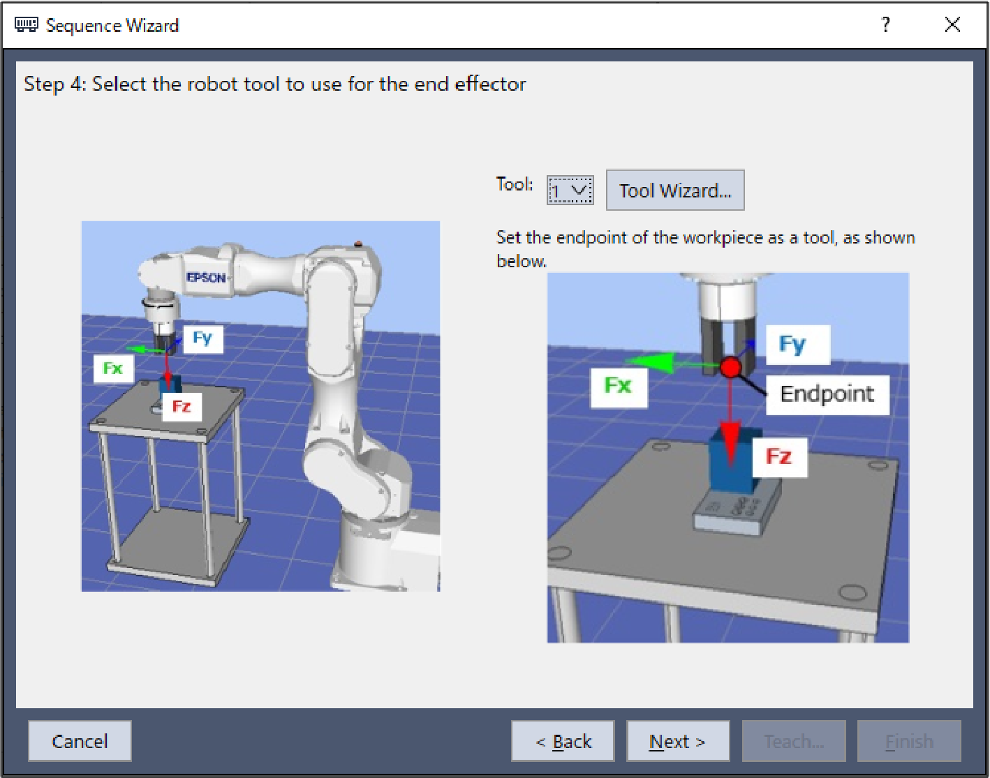 ItemValueDescription
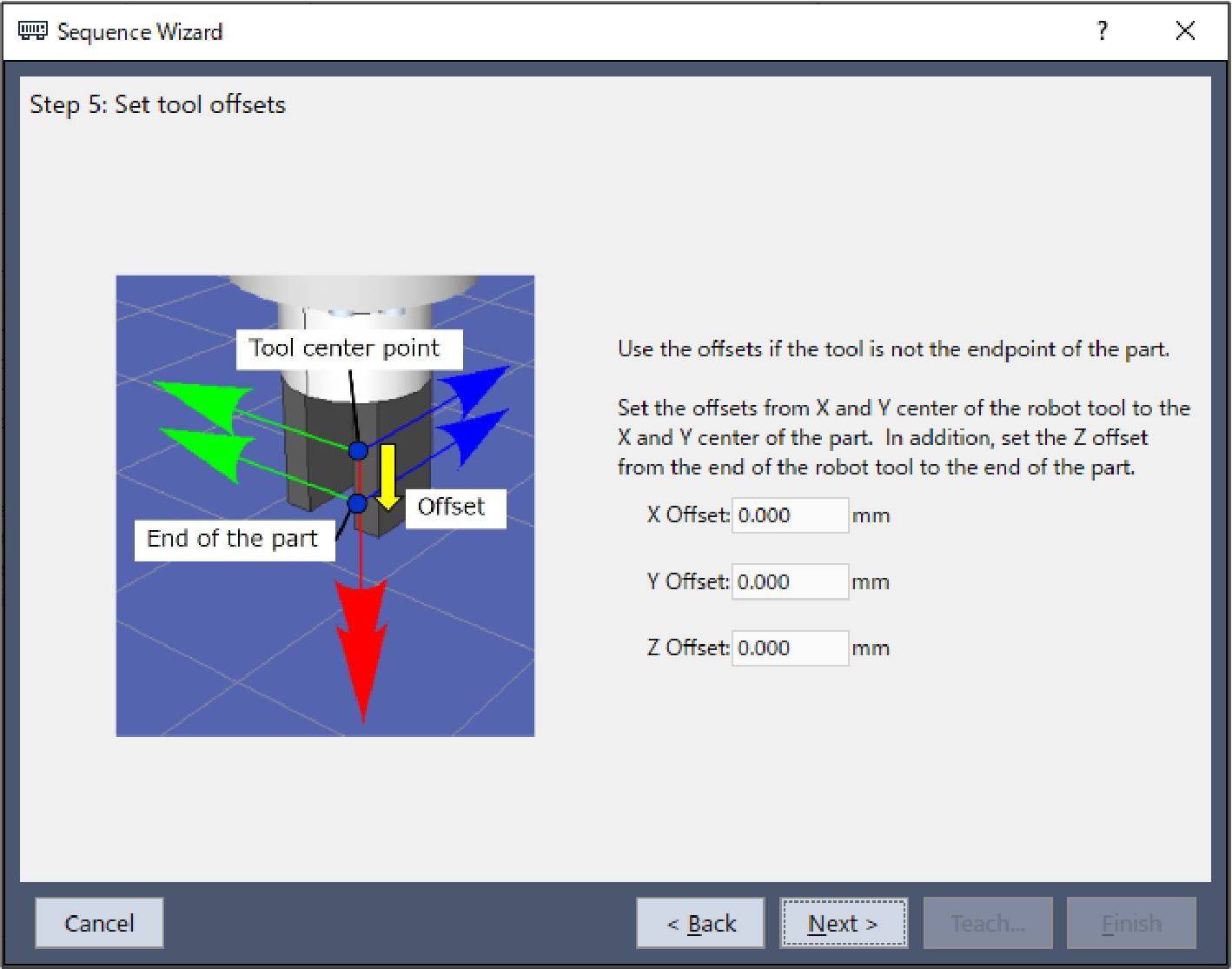
Tool 1 Specify the number set for the tool used in this sequence. - The [Step 5: Set tool offsets] dialog box is displayed.
Set tool offset values. These settings can be left as the default values and do not need to be changed.
Click the [Next] button.
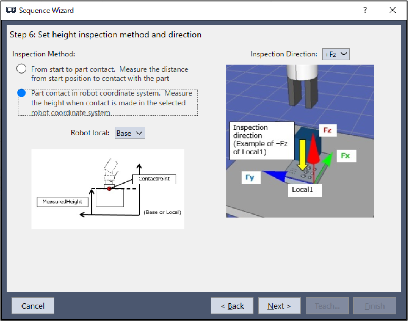
- The [Step 6: Set height inspection method and direction] dialog box is displayed.
Select the [Part contact in robot coordinate system] button for [Inspection Method], and select "Base" for [Robot local].
This tutorial performs the height inspection to +Z direction of the tool.
When the Z axis of the tool coordinate system is in the vertical-downward direction, it is parallel and opposite to the Z axis of the base coordinate system. Select the -Fz direction in the base coordinate system as the inspecting direction.
Click the [Next] button.
- The [Step 7: Configure the reference position and tolerance] dialog box is displayed.
Change the properties according to the table below.
Click the [Next] button.
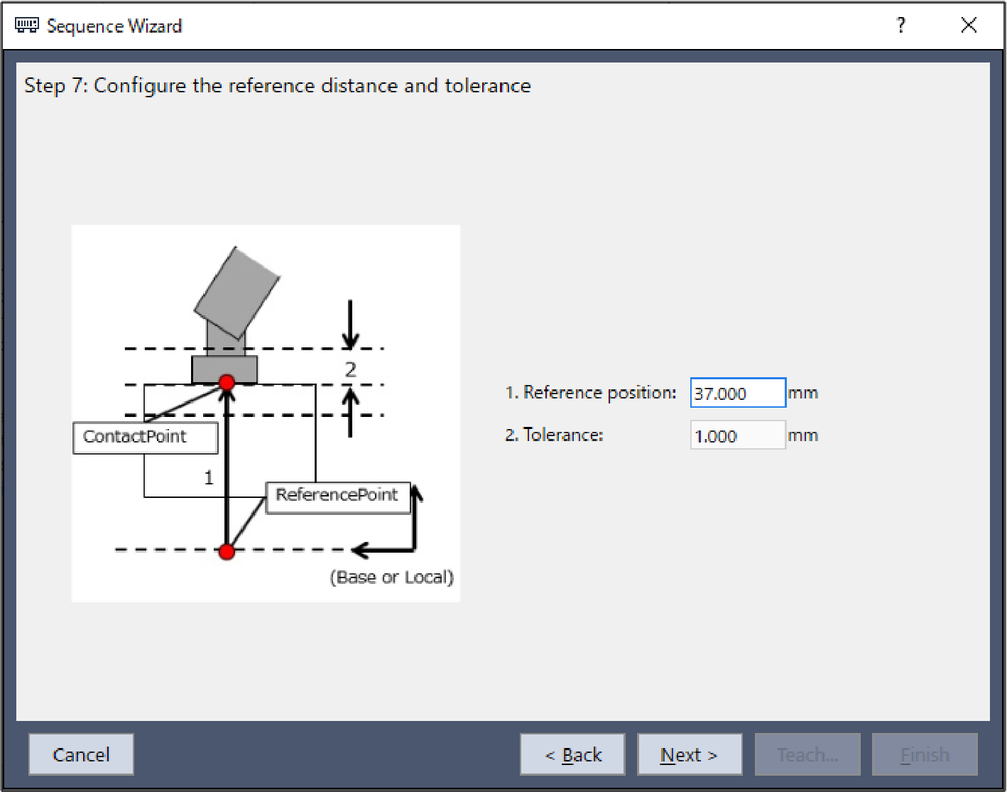 ItemValueDescription
Reference position 37 Set the position of the Z coordinate that determine the height inspecting process has ended successfully on the base coordinate system when the tool coordinate system is set to 1.
Set the position according to your operating environment.
The position is set to 37mm in this tutorial.
Effective Range 1 Set the tolerance of the position to be determined that the height inspection has ended successfully.
Set this to 1mm.
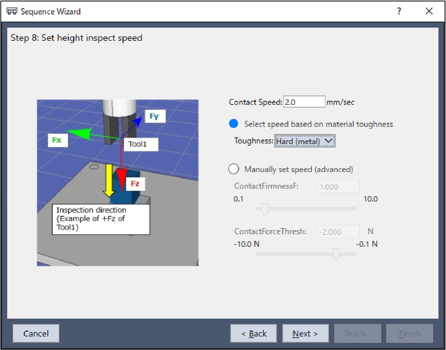
- The [Step 8: Set height inspect speed] dialog box is displayed.
Select [Select speed based on material toughness].
Change the properties according to the table below.
Click the [Next] button.
 ItemValueDescription
Toughness Hard(Metal) Set contact speed the firmness of the Work piece.
When selecting Hard (Metal), the contact speed is 2mm/sec.
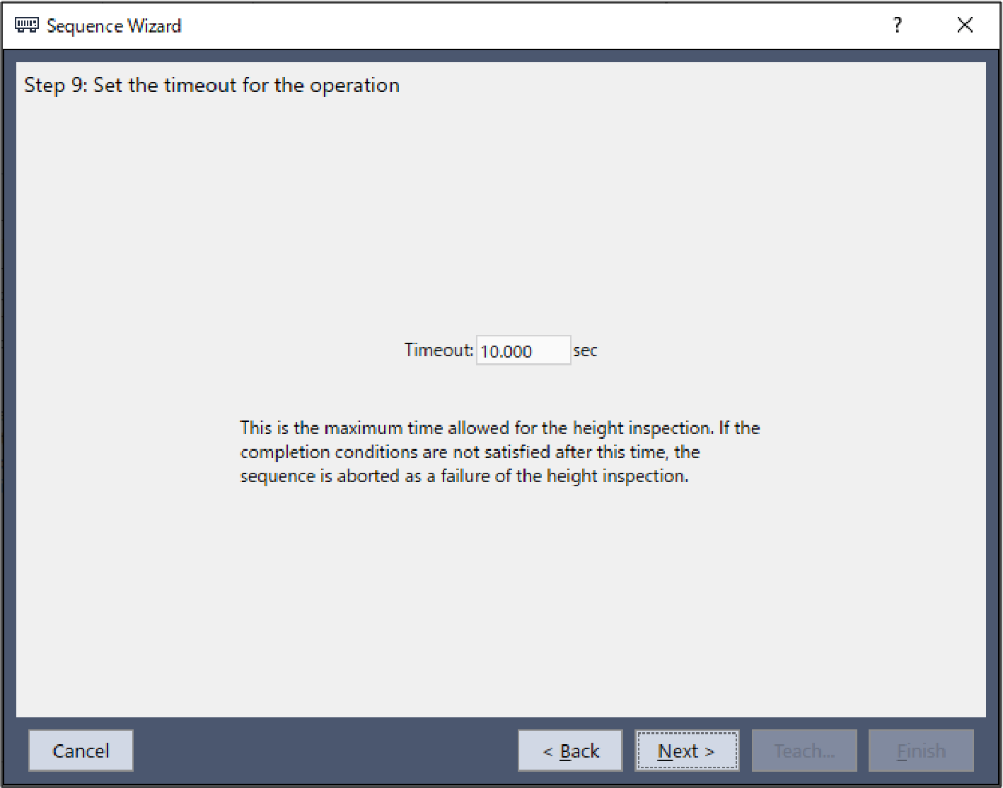
- The [Step 9: Set the timeout for the operation] dialog box is displayed.
Change the properties according to the table below.
Click the [Next] button.
 ItemValueDescription
Timeout 10 Set the time-out duration.
Set this to 10 seconds.
- The [Finish] dialog box is displayed. Click the [Finish] button.
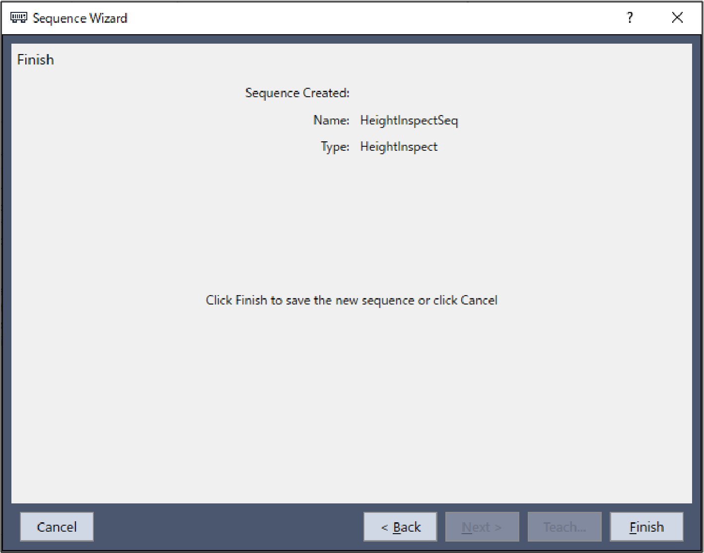
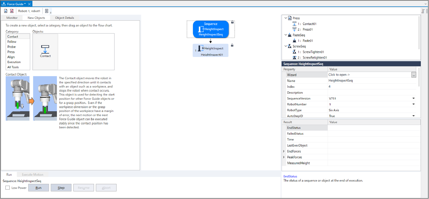
Check to make sure the [HeightInspectSeq] sequence has been created.
Setting Confirmation
The following describes how to check whether the settings for inspecting direction are correct by using a simulator.
- Click Epson RC+ menu-[Tools]-[Simulator].
The [Simulator] window is displayed. - Click the object tree-[Tool].
Place a checkmark in the "No.1"-[Visible] check box. An arrow for "Tool 1" is displayed. - Click the object tree-[Force]-[Force Guide]-[HeightInspectSeq].
Place a checkmark in the "HeightInspect01"-[Visible] check box.
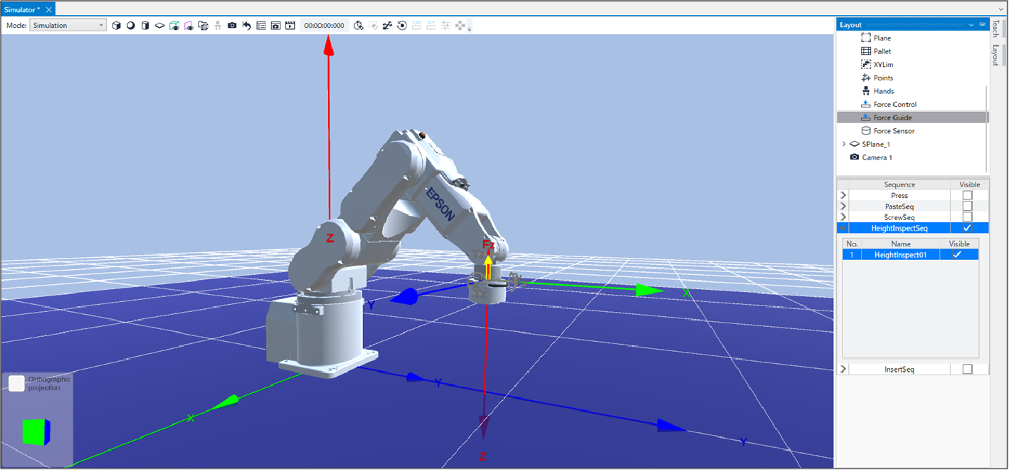
Confirm that the yellow arrow direction is the same as the inspecting direction.
Motion by Force Guidance Function
The following describes how to run the created HeightInspect sequence by Epson RC+.
- Open the [Force Guide] window.
- Select the [Jog] tab.
- Click the [POWER HIGH] button.
If the robot might break the workpiece, operate in "Low Power Mode". - Click the [Run] button.
Program is compiled and transmitted to the Robot Controller.
If the setting is not correct, an error occurs. Check the settings so far and follow the error message to modify the parameters.
- When the operation is performed properly,
 is displayed on the upper left of the flowchart and the height inspection is completed.
Return to the Non-Contact State
After completing HeightInspect sequence, force continues to be applied to between the robot and the workpiece.
To prevent the robot and the end effector from malfunction or damages, after the operation ends, make sure that no force is applied to the object.
If it is obvious that no force is applied to the object, you can omit this step.
Steps to return to a non-contact state are as follows:
- Click Epson RC+ menu-[Tools]-[Robot Manager]-[Jog & Teach] panel-[Jog] group and perform jog motion manually to move the robot away from the object.
- Click Epson RC+ menu-[Tools]-[Robot Manager]-[Jog & Teach] panel-[Execute Motion] tab and move the robot away from the object.
- Execute Move command on [Command Window] and move the robot away from the object.
- Add SPELFunc object after HeightInspect object, and automatically move the robot away from the object at the end of the force guide sequence.
The following describes how to return to non-contact state by clicking [Robot Manager]-[Jog & Teach]-[Execute Motion] tab.
- Display the [Robot Manager] dialog box.
- Click the [Jog & Teach] tab.
- Select the [Execute Motion] tab.
- Select "Move" in [Command].
- Select "P1" in [Destination].
- Click the [Execute] button.
The robot moves to the start point: P1. Now, it is the non-contact state.
Motion Analysis by Monitor
The following describes how to use Epson RC+ to check the operation results of a force guide sequence.
- Open the [Force Guide] window.
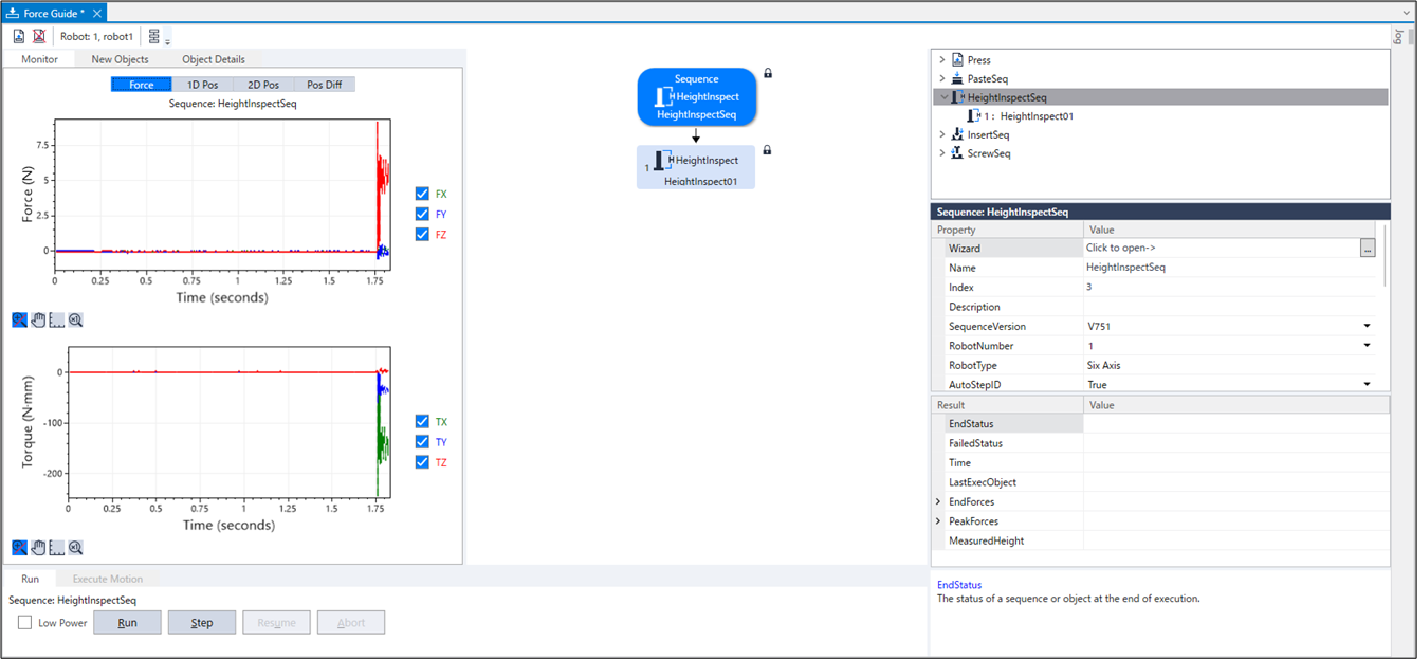
- Click the sequence flow of [HeightInspect].
- The operation results (Passed / Failed), detected force values at the end of the robot motion, and the time that was required are displayed under [Result].
- The graphs of force and position during the [HeightInspect] sequence execution are displayed in [Monitor].
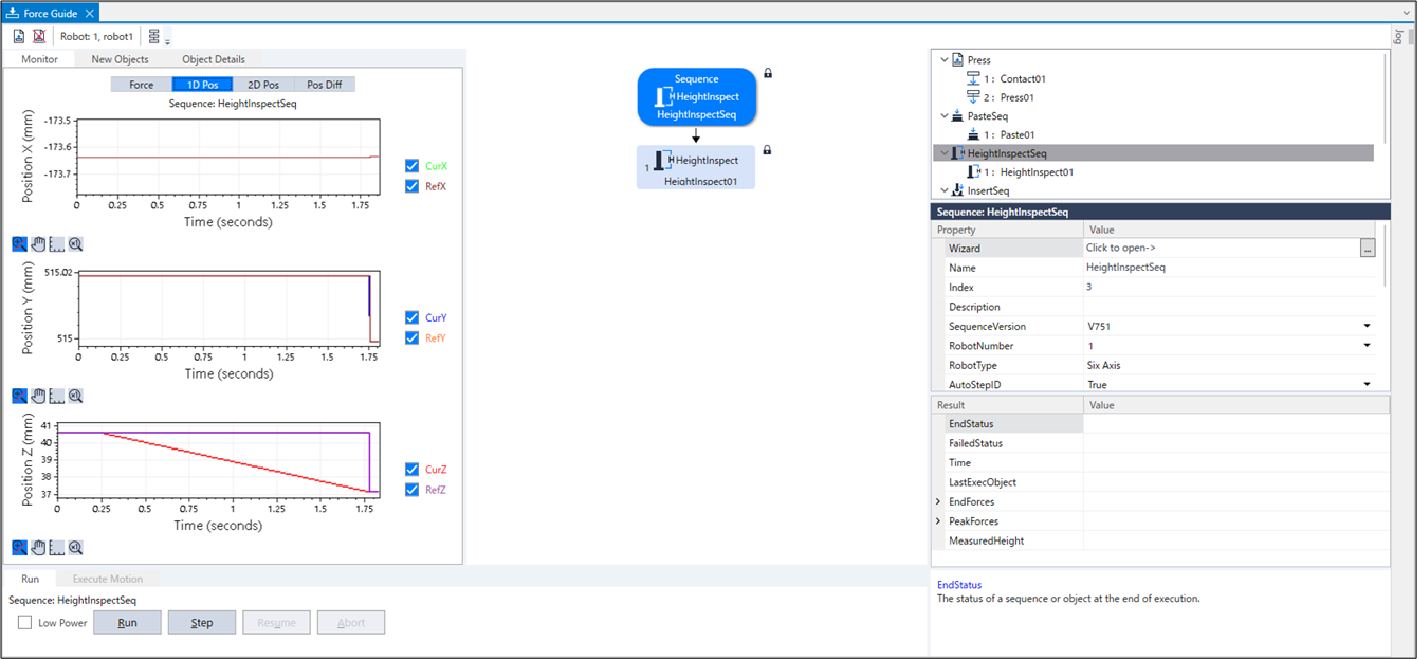
[1D Pos] tab
It is a graph for analysis. (horizontal axis: Time, vertical axis: Position)
The robot moves in the direction where CurZ of the position Z chart is getting low (small).
Since "Step 1" ends near 1.7 seconds and the force control has been completed, you can see that the value of RefZ (reference position) is falling (jumping) straight down to CurZ (current position).
[2D Pos] tab
It is a graph for analysis. (horizontal axis, vertical axis: Position)
It is not required for the height inspection in this tutorial since the robot does not move in the X or Y directions.[Pos Diff] tab
It shows the relative change of positions due to the force control.
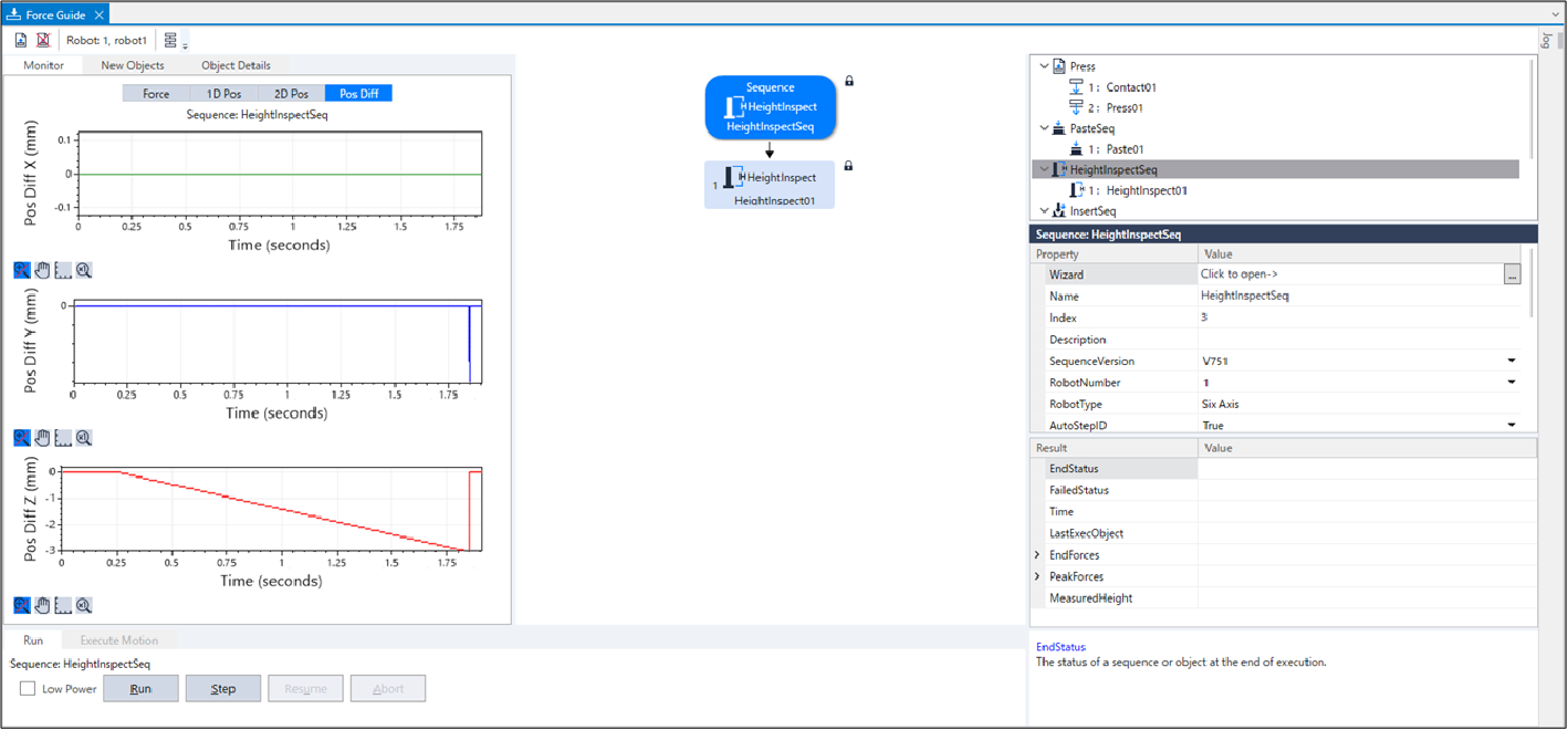
Change the unit of the graph and check the changes of force or positions.
If it is not inspected correctly, the setting may not be correct.
Refer to the following and check the procedures of the tutorial.
- Whether a contacting direction is correct
- Whether the set reference position is largely moved from the point where the robot contacts the object to be inspected
This ends the HeightInspect sequence tutorial.