Confirmation of Tool Setting
The following describes tool setting procedures.
In the Paste sequence, you need to consider the behavior of the actual pasting direction and the current tool settings.
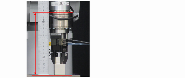
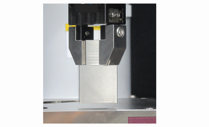
Use a metal scale to measure the distance from the J6 flange plane to the pasting surface.
Execute the following in [Command Window].
In "Length", enter the value measured in the procedure (1).> Tlset 1,XY(0,0,Length,0,0,0)Click Epson RC+ menu-[Tools]-[Simulator].
The [Simulator] window is displayed.Select the object tree-[Manipulator Name]-[Tool].
Place a checkmark in "No.1"-[Visible] check box.
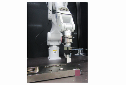
To confirm that the tool setting is correct, compare the display of the [Simulator] window and the orientation of the actual robot.
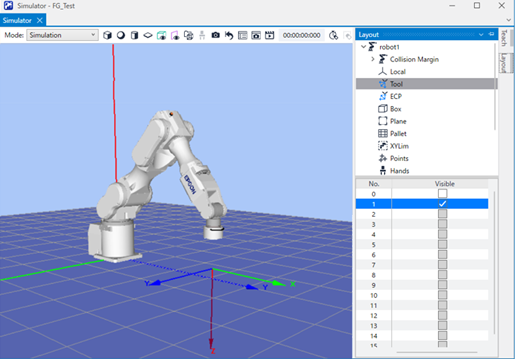
According to the display of the [Simulator] window, you will see that pasting is performed to the +Z direction of the tool.
Position Teaching
The following describes how to teach a sequence start position of Paste sequence.
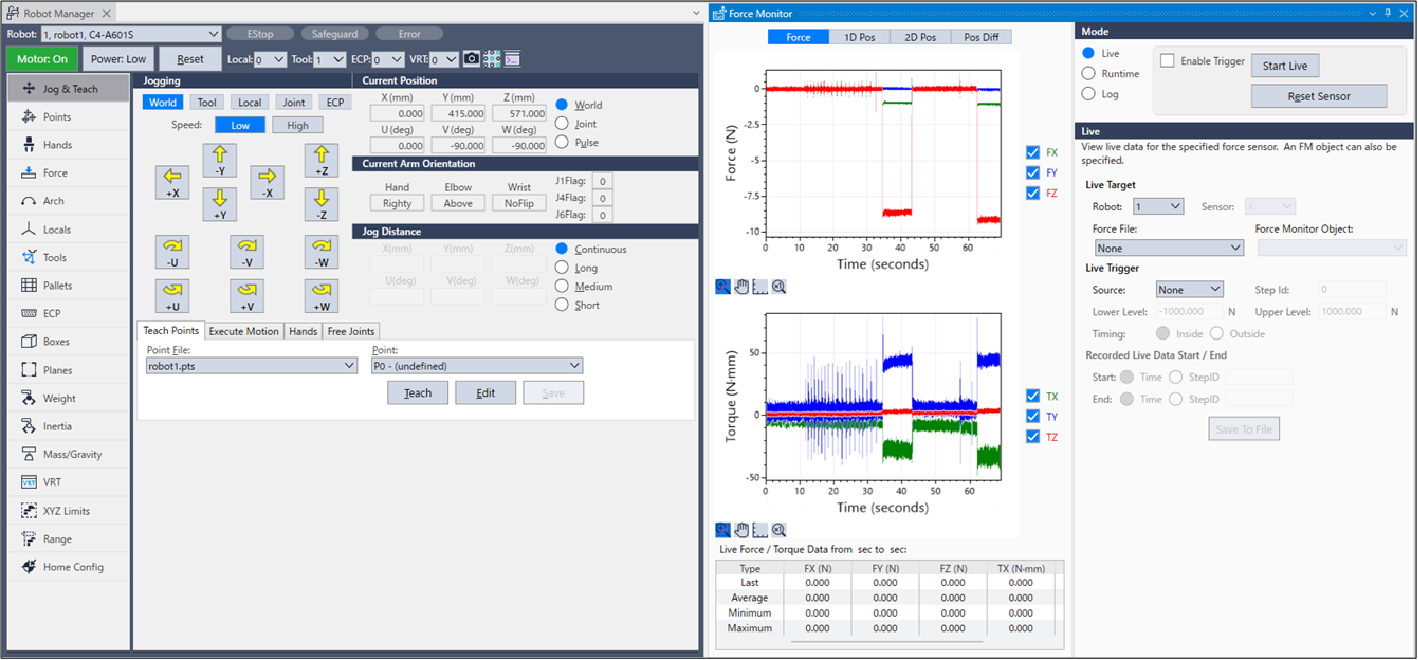
Click Epson RC+ menu-[Tools]-[Robot Manager]. The [Robot Manager] dialog box appears.
Select [Jog & Teach] and open the panel.
Select "1" on [Tool].
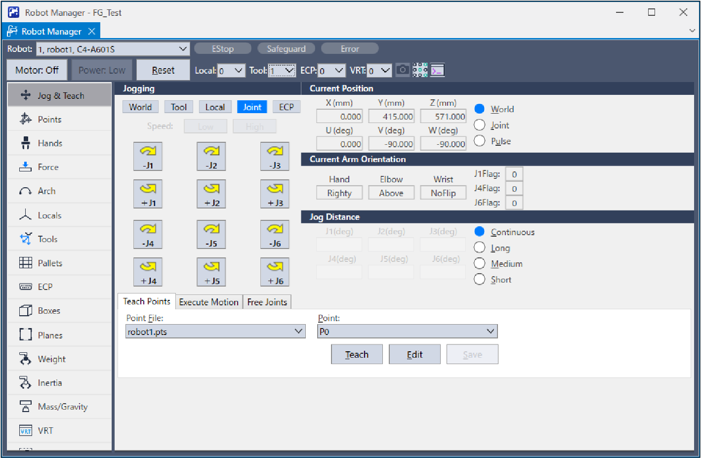
Use the Jog button to move the robot about 2mm above the pasting position.
Execute the following command in the command window if necessary.> Go Align(Here)By executing the above command, the robot will be a parallel orientation against the Base coordinate system based on the current position. The robot can move with the robot and the point facing each other.
For details, refer to the following manual:
"Epson RC+ SPEL+ Language Reference" Align Function
Select Epson RC+ menu-[Tools]-[Force Monitor].
The [Force Monitor] dialog box is displayed.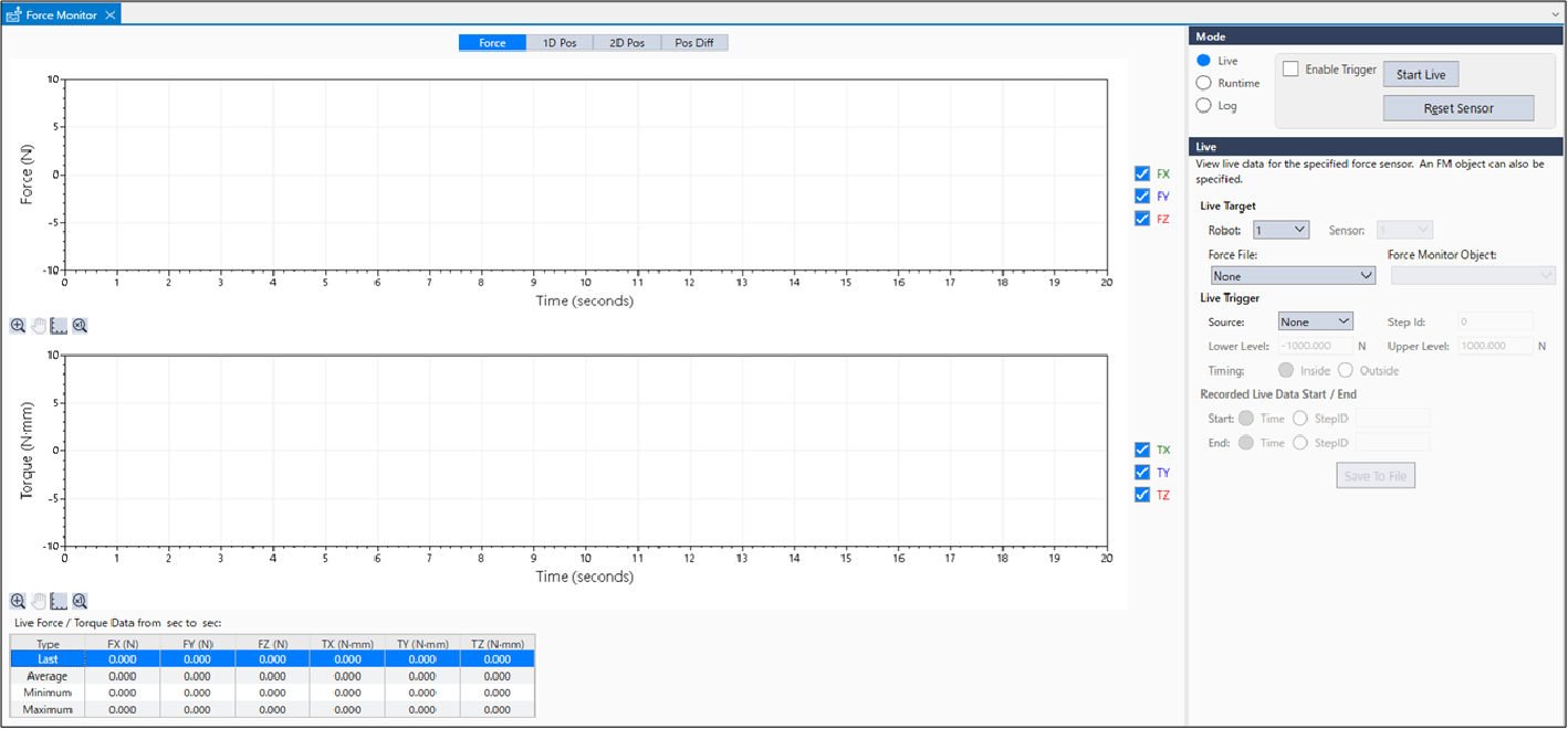
Select [Short] button on [Jog Distance].
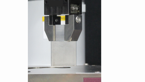
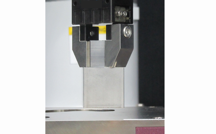
Click the Jog button several times to move the robot to -Z direction until the pasting surface contacts with the workpiece to be pasted. When the robot contacts with the object, output value of Force Sensor changes. Check the changes of monitor value by the timing of the jog motion.
Select the [Medium] button on [Jog Distance].
Click the Jog button five times and move the robot 5mm to +Z direction to put the workpiece in a non-contact state.
This is a start position of sequence and a position where the Force Sensor is reset.Select "P1" in the [Point] dropdown.
Enter "PasteStart" in [Point Label]. Click the [OK] button.
Click Epson RC+ menu-[File]-[Save All].
The file is saved.
Sequence wizard
The following describes how to create a Paste sequence of the system force guide sequences.
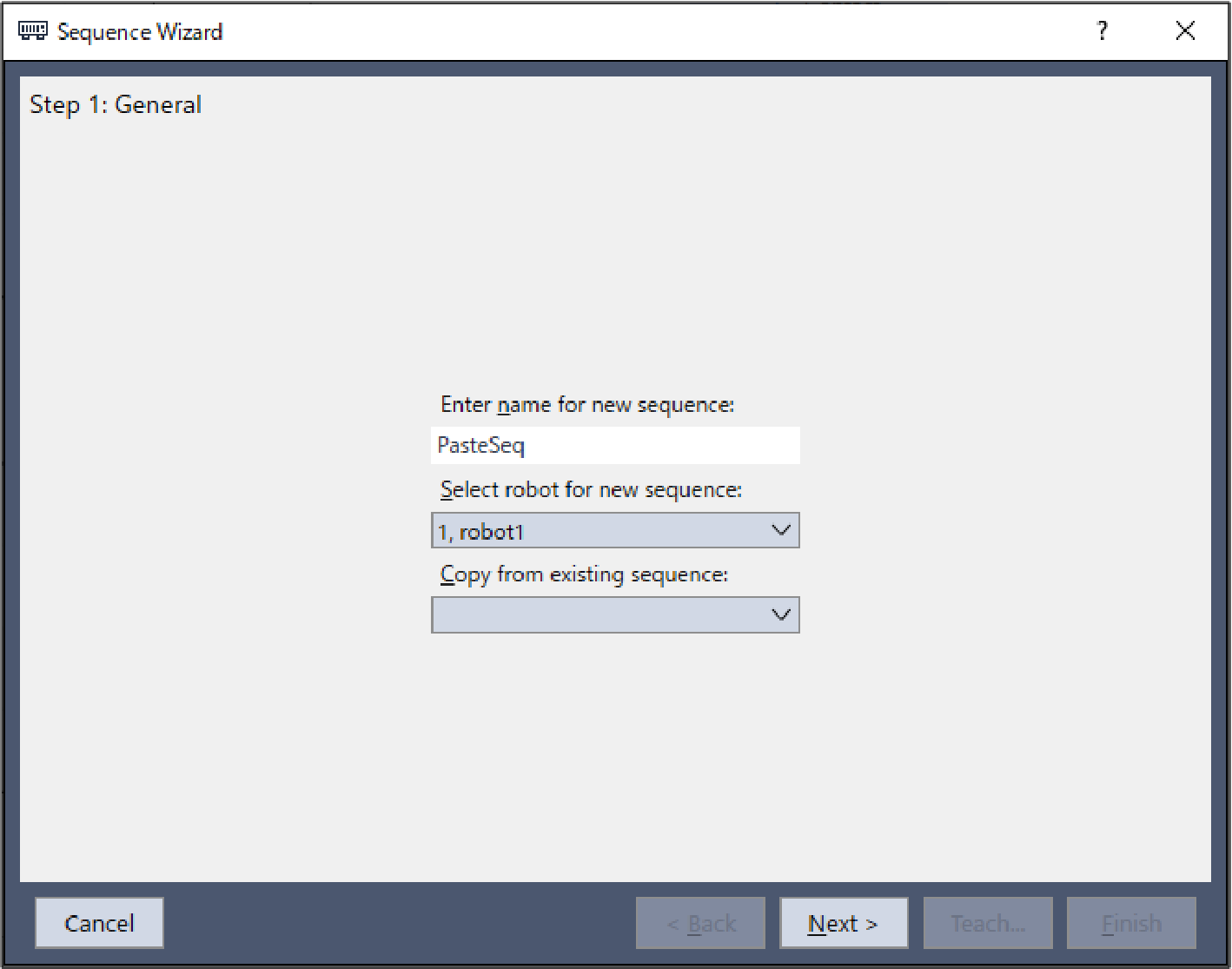
Enter "PasteSeq" in the [Enter name for new sequence] box.
Click the [Next] button.
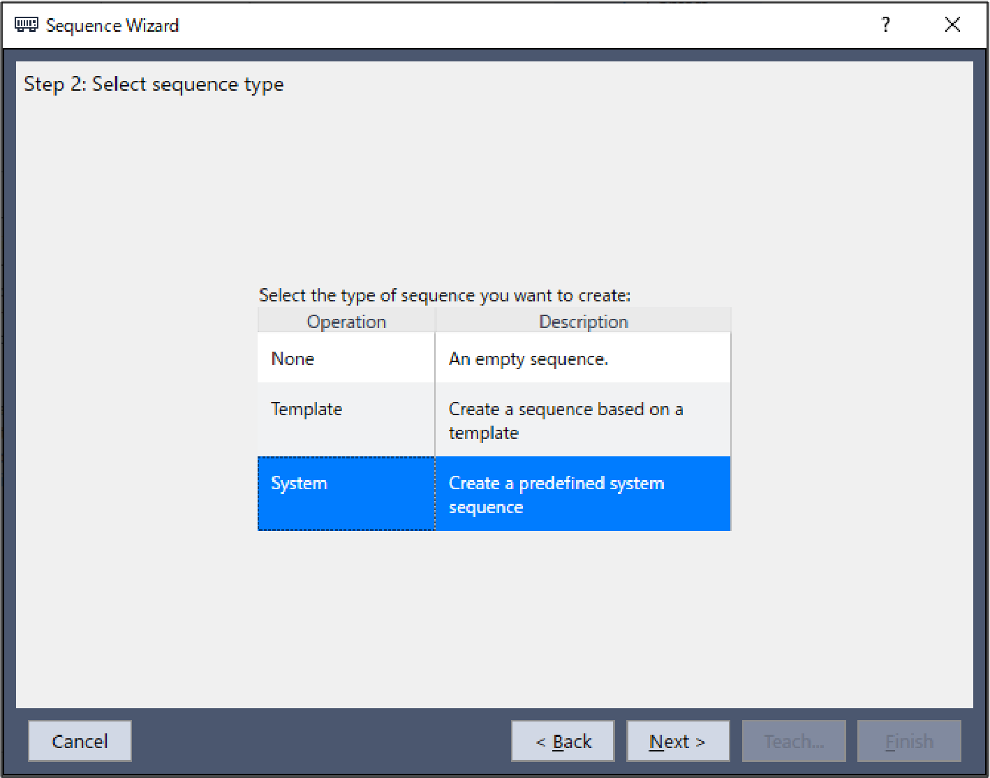
The [Step 2: Select sequence type] dialog box is displayed. Select [System]. Click the [Next] button.
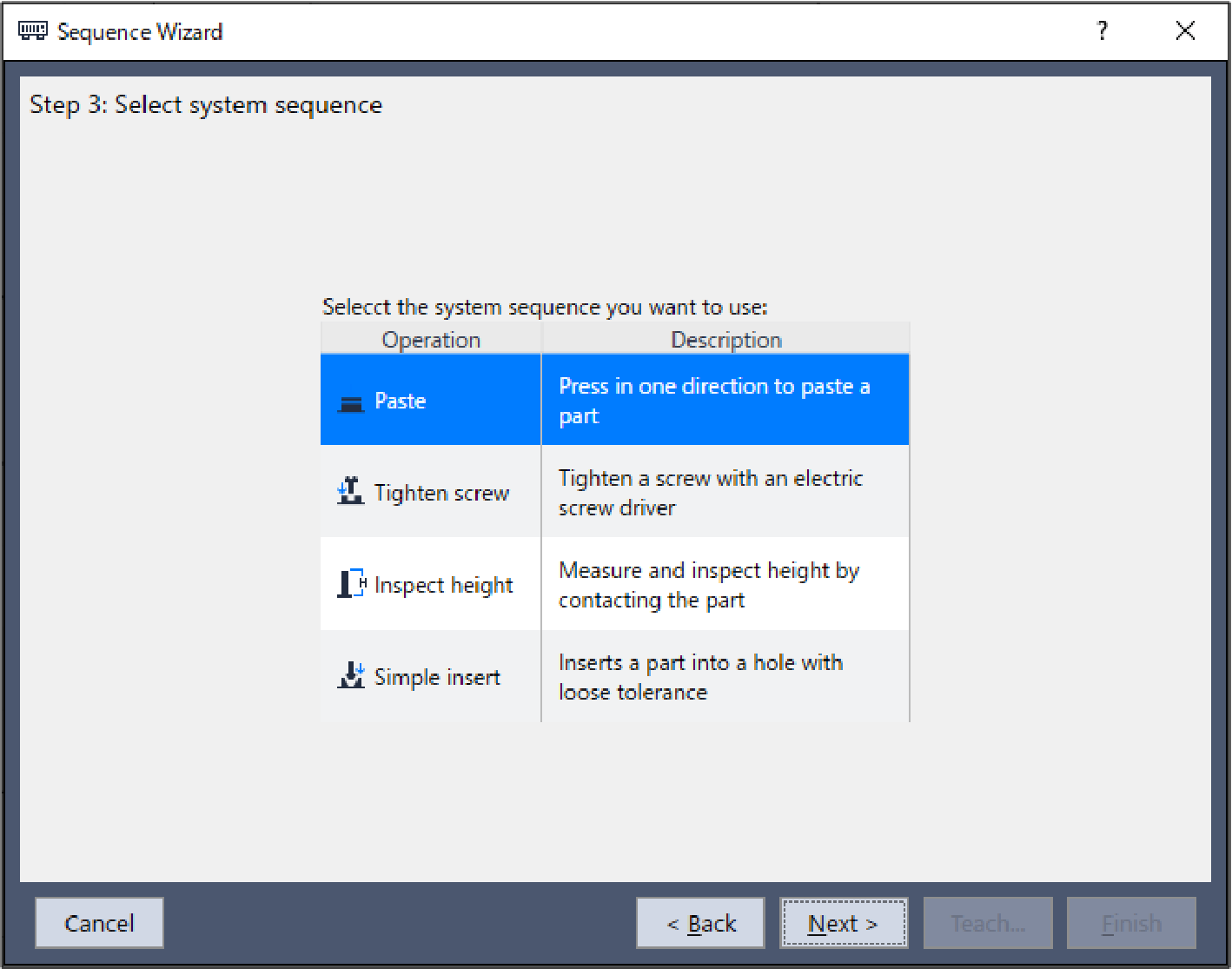
The [Step 3: Select system sequence] dialog box is displayed. Select [Paste]. Click the [Next] button.
The [Step 4: Select the robot tool to use for the end effector] dialog box is displayed. Change the properties according to the table below. Click the [Next] button.
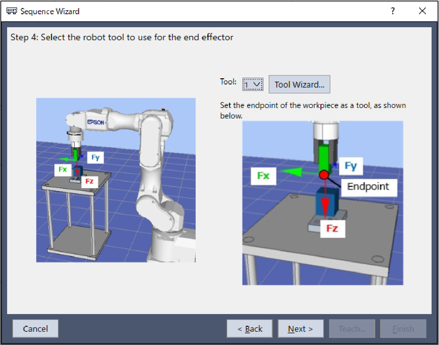
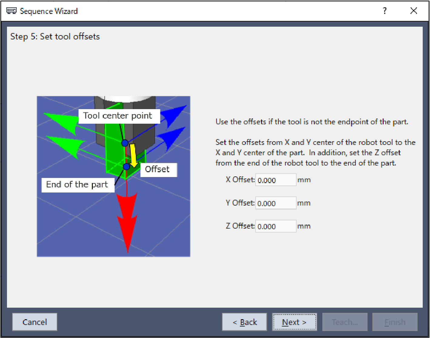
Item Value Description Tool 1 Specify the number set for the tool used in this sequence. The [Step 5: Set tool offsets] dialog box is displayed.
Set tool offset values. These values can be left as the default values and do not need to be changed.
Click the [Next] button.
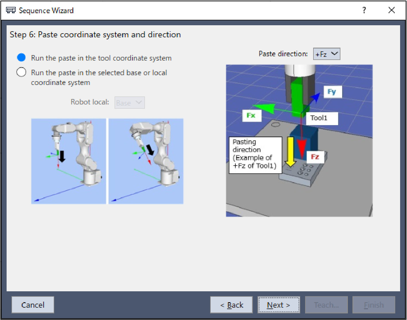
The [Step 6: Paste coordinate system and direction] dialog box is displayed.
As the pasting direction is in the +Fz direction in the tool coordinate system, these values can be left as the default values and do not need to be changed.
Click the [Next] button.
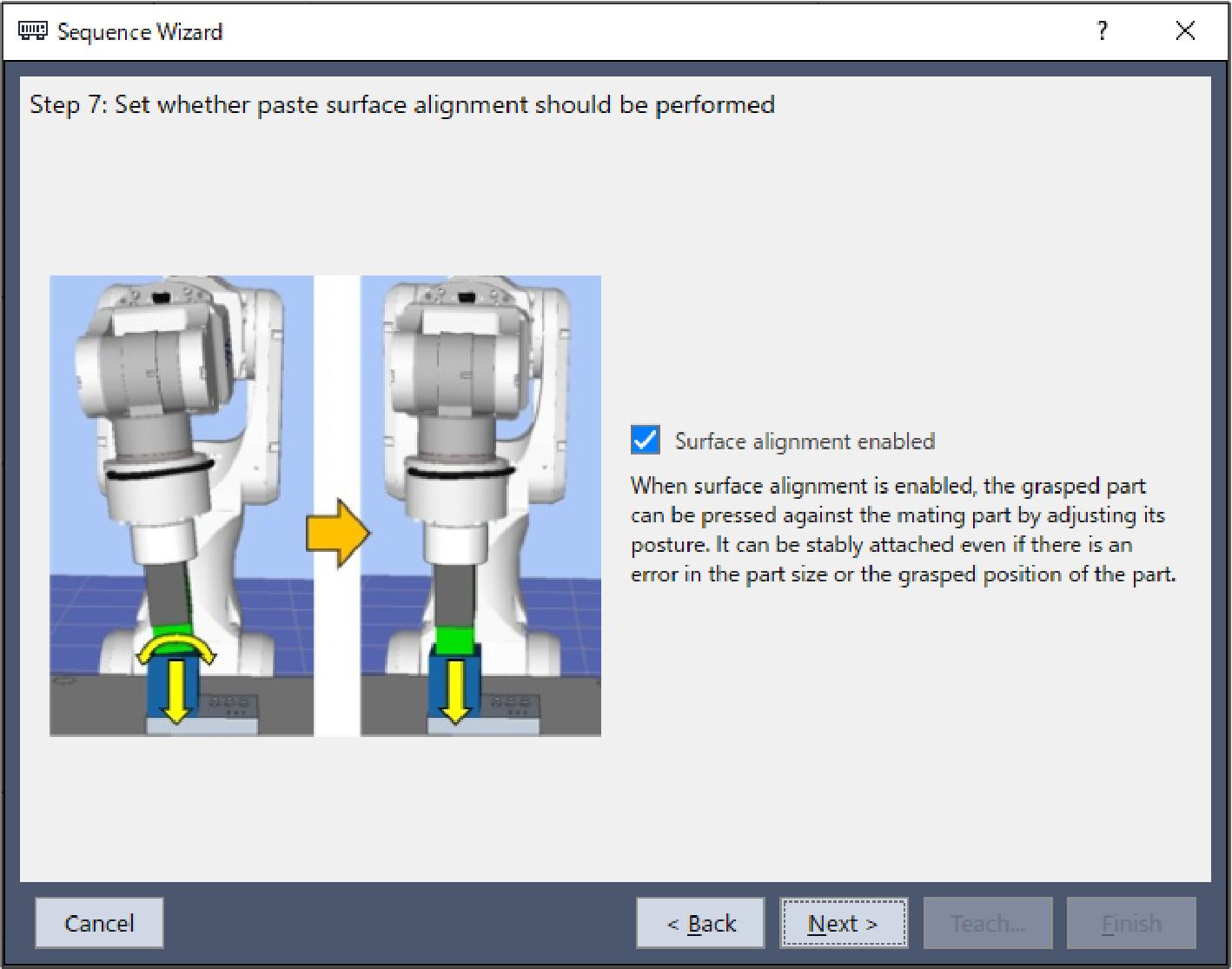
The [Step 7: Set whether paste surface alignment should be performed] dialog box is displayed.
Set whether to enable surface alignment.
As surface alignment is performed, this value can be left as the default value and does not need to be changed.
Click the [Next] button.
The [Step 8: Set paste approach distance] dialog box is displayed.
Change the properties according to the table below. Click the [Next] button.
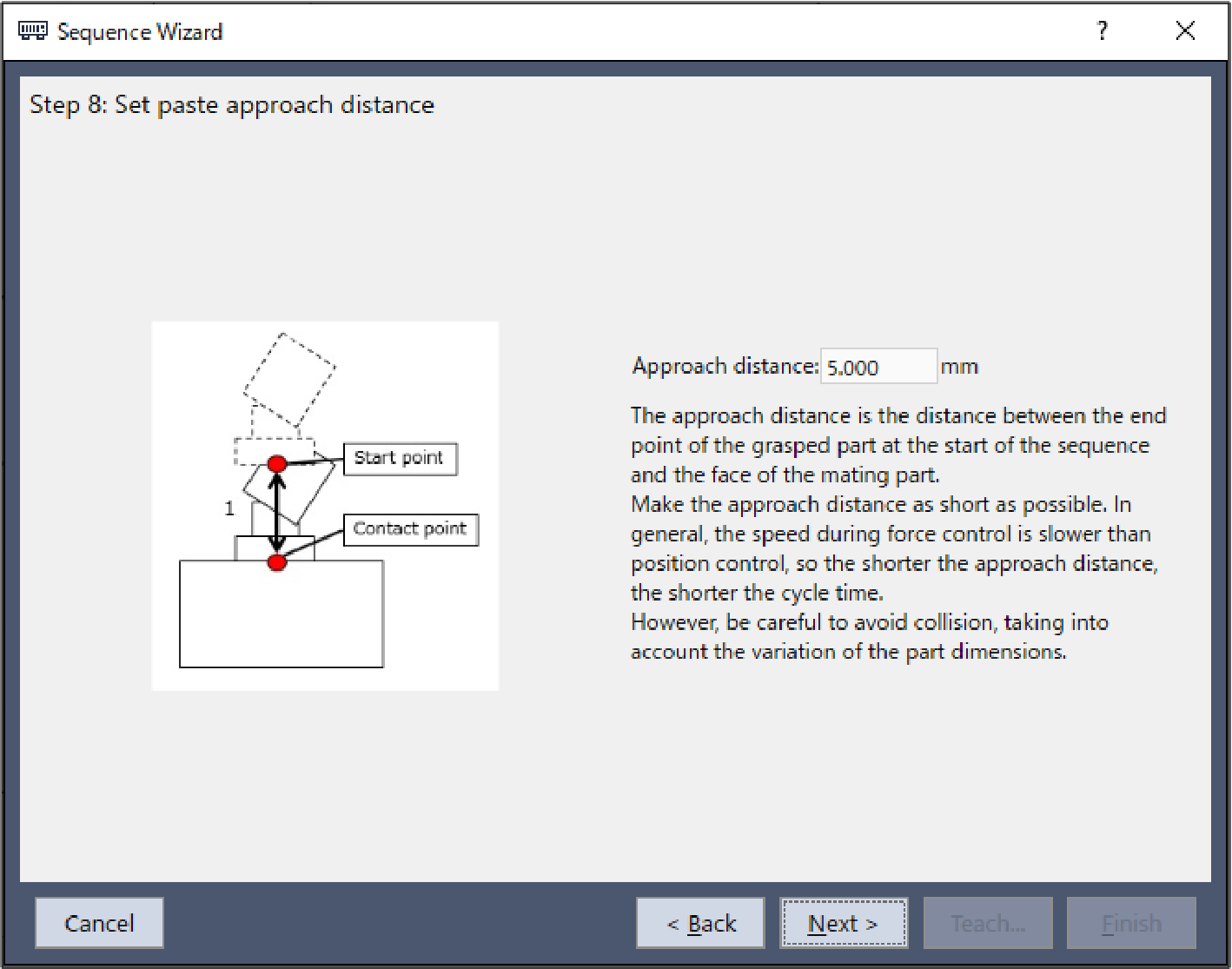
Item Value Description Approach distance 5 Set the distance from the end of the gripped workpiece to the object face to be pasted.
Set this to 5mm.
The [Step 9: Set paste force] dialog box is displayed. Change the properties according to the table below. Click the [Next] button.
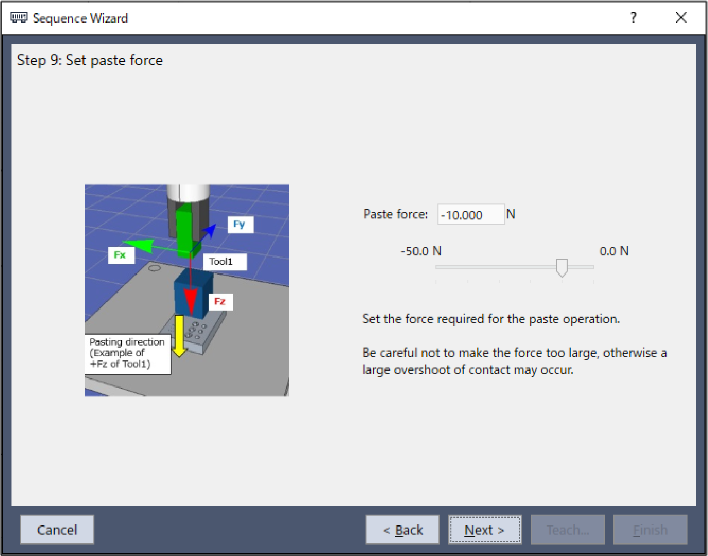
Item Value Description Paste force -10 Set the paste force.
Set this to -10N.
Set this to a tolerable value considering the workpiece in use.
The [Step 10: Set paste firmness] dialog box is displayed.
Select [Set align firmness manually (advanced)].
Change the properties according to the table below.
Click the [Next] button.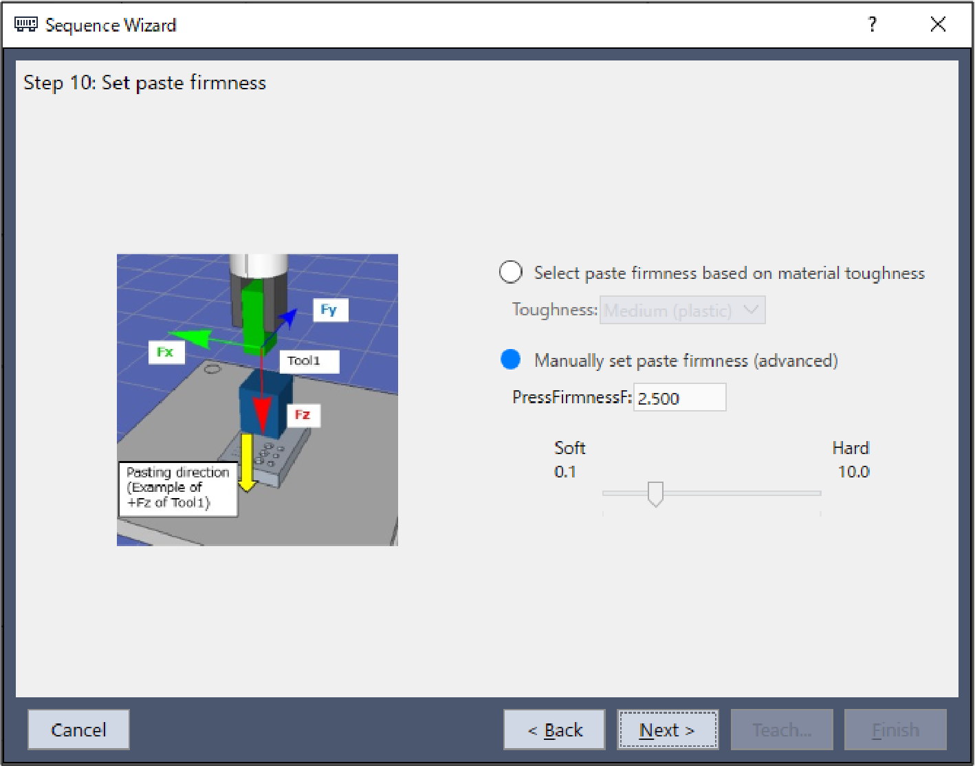
Item Value Description PressFirmnessF 2.5 Set the firmness of the force control function in the direction of pasting.
Set this to 2.5.
The [Step 11: Set paste surface alignment firmness] dialog box is displayed.
Select [Set align firmness manually (advanced)].
Change the properties according to the table below.
Click the [Next] button.
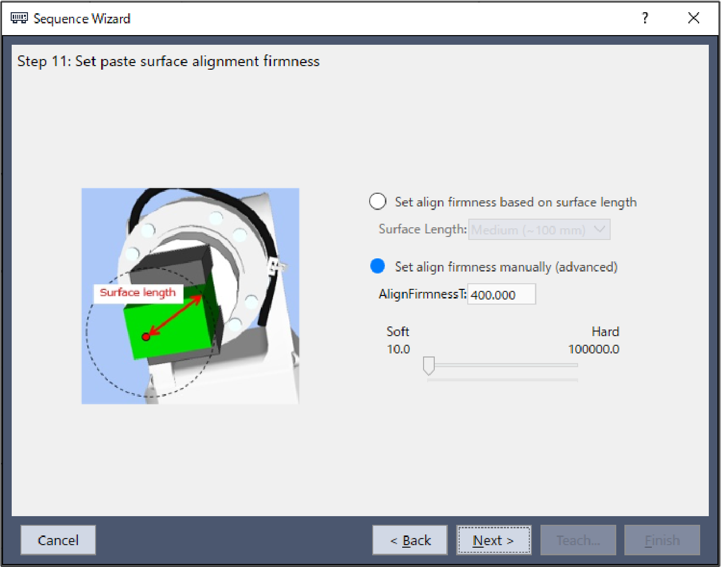
Item Value Description AlignFirmnessT 400 Set the firmness of the force control function in the direction of surface alignment.
Set this to 400.
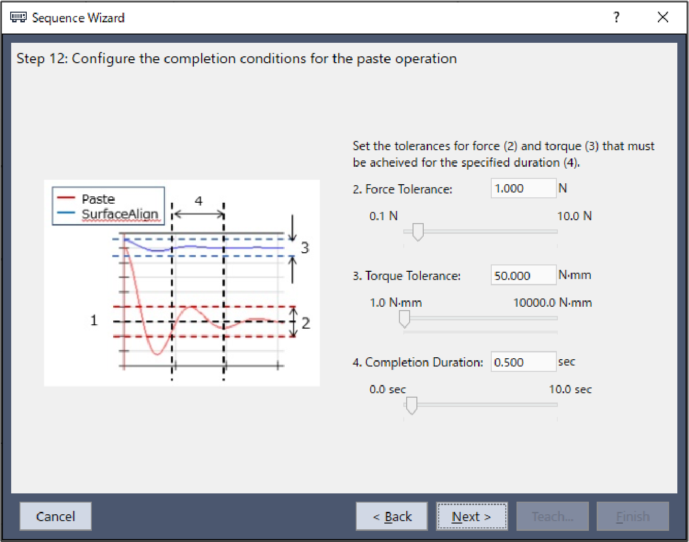
The [Step 12: Configure the completion conditions for the paste operation] dialog box is displayed.
Change the properties according to the table below.
Click the [Next] button.
 ItemValueDescription
Force Tolerance 1 Set the range to use as the end condition related to force.
Set this to 1N.
Torque Tolerance 50 Set the range to use as the end condition related to torque.
Set this to 50 Nmm.
Completion Duration 0.5 Set the duration at which end conditions are deemed to have been met.
Set this to 0.5 seconds.
The [Step 13: Set the timeout for the operation] dialog box is displayed.
Change the properties according to the table below. Click the [Next] button.
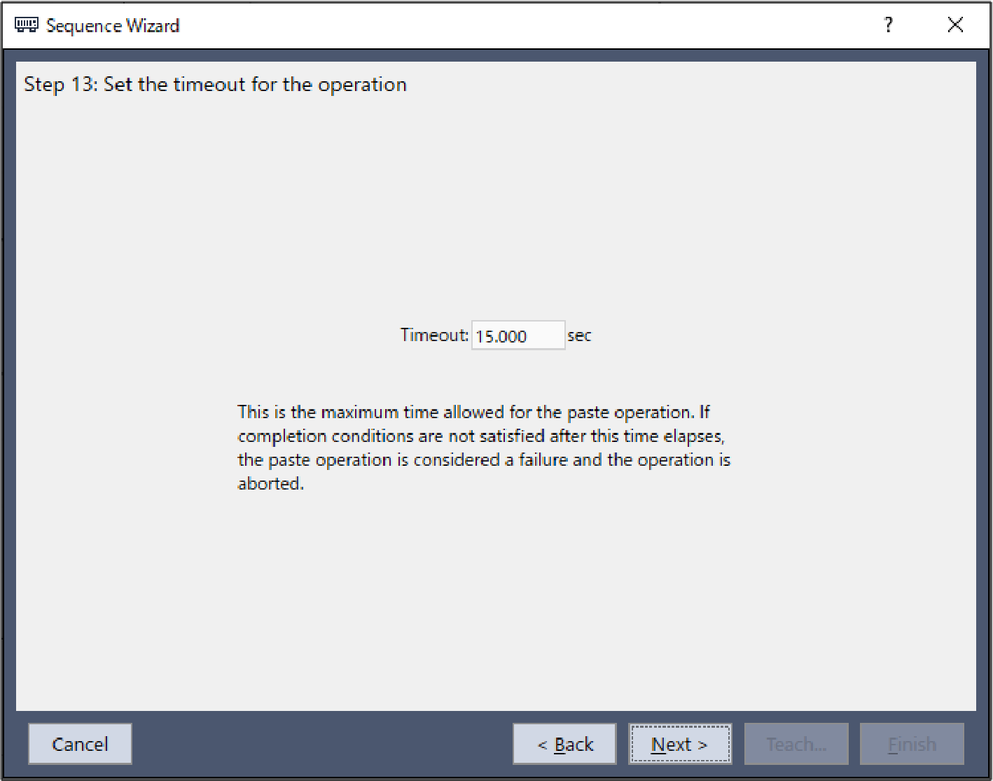
Item Value Description Timeout 15 Set the time-out duration.
Set this to 15 seconds.
The [Finish] dialog box is displayed.
Click the [Finish] button.
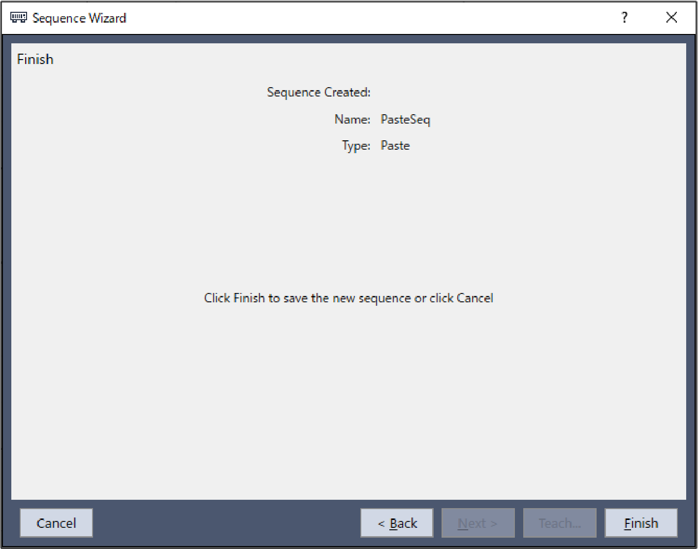
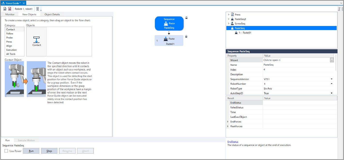
Check that the [PasteSeq] sequence has been created.
Setting Confirmation
The following describes how to check whether the settings for pasting direction are correct by using a simulator.
- Click Epson RC+ menu-[Tools]-[Simulator].
The [Simulator] window is displayed. - Click the object tree-[Tool].
Place a checkmark in the "No.1"-[Visible] check box. An arrow for "Tool 1" is displayed. - Click the object tree-[Force]-[Force Guide]-[PasteSeq].
Place a checkmark in the "Paste01"-[Visible] check box.
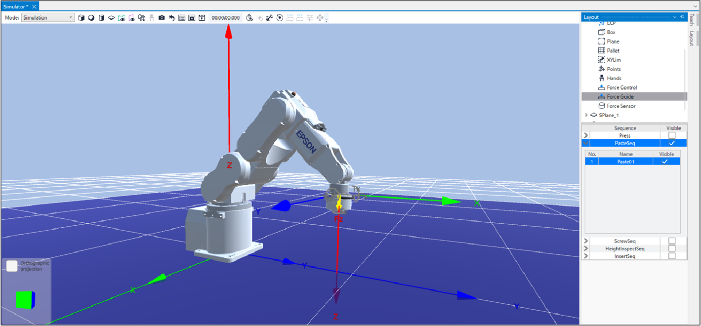
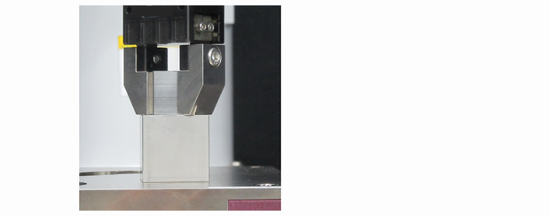
Confirm that the yellow arrow direction is the same as the pasting direction.
Motion by Force Guidance Function
The following describes how to run the created Paste sequence by Epson RC+.
- Open the [Force Guide] window.
- Select the [Jog] tab.
- Click the [POWER HIGH] button.
If the robot might break the workpiece, operate in "Low Power Mode". - Click the [Execute] button.
Program is compiled and transmitted to the Robot Controller.
If the setting is not correct, an error occurs.
Check the settings so far and follow the error message to modify the parameters. - When the operation is performed properly,
 is displayed on the upper left of the flowchart and the pasting is completed.
Return to the Non-Contact State
After completing the Paste sequence, force continues to be applied to between the robot and the workpiece.
To prevent the robot and the end effector from malfunction or damages, after the operation ends, make sure that no force is applied to the object.
If it is obvious that no force is applied to the object, you can omit this step.
Steps to return to a non-contact state are as follows:
- Click Epson RC+ menu-[Tools]-[Robot Manager]-[Jog & Teach] panel-[Jog] group and perform jog motion manually to move the robot away from the object.
- Click Epson RC+ menu-[Tools]-[Robot Manager]-[Jog & Teach] panel-[Execute Motion] tab and move the robot away from the object.
- Execute Move command on [Command Window] and move the robot away from the object.
- Add SPELFunc object after Press object, and automatically move the robot away from the object at the end of the force guide sequence.
The following describes how to return to non-contact state by clicking [Robot Manager]-[Jog & Teach]-[Execute Motion] tab.
- Display the [Robot Manager] dialog box.
- Click the [Jog & Teach] tab.
- Select the [Execute Motion] tab.
- Select "Move" in [Command].
- Select "P1" in [Destination].
- Click the [Execute] button.
The robot moves to the start point: P1. Now, it is the non-contact state.
Motion Analysis by Monitor
The following described how to check the motion results of force guide sequence by Epson RC+.
- Open the [Force Guide] window.
- Click the sequence flow of [PasteSeq].
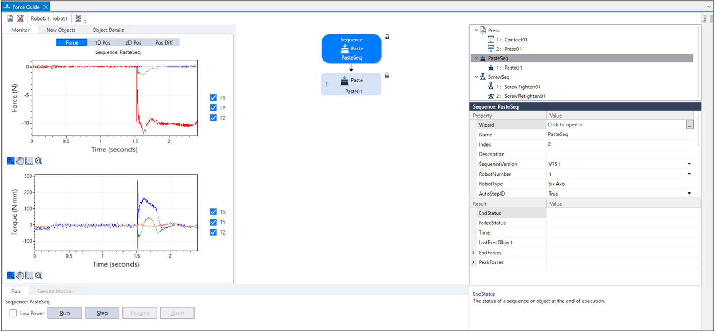
- Select the [Monitor] tab. Select the [Force] tab.
Force and position during the [PasteSeq] sequence execution are displayed in the graph.
- Select the [1D Pos] tab.
Graph for analysis is displayed. (horizontal axis: Time, vertical axis: Position)
As you can see by looking the Position Z graph, CurZ (current position) is lowered by about 5mm. It indicates that the robot moves 5mm of the approach distance in the pasting direction.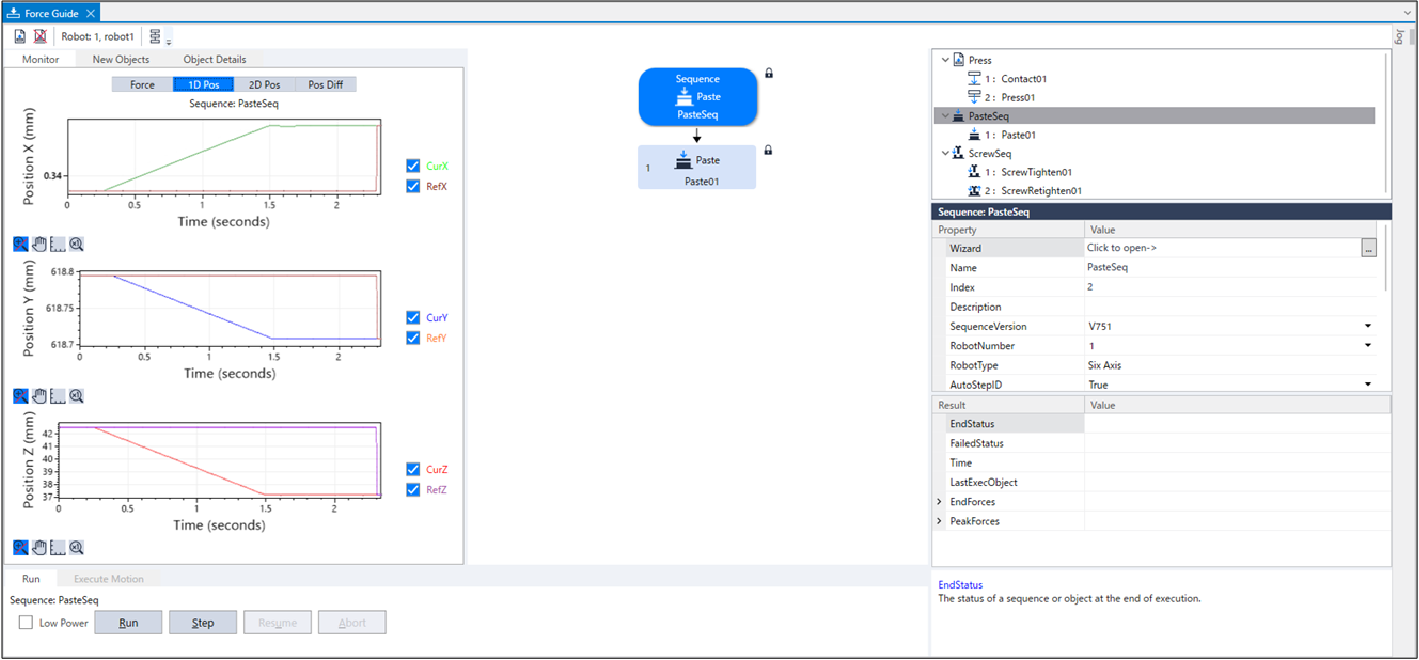
- Select the [2D Pos] tab.
Graph for analysis is displayed. (horizontal axis, vertical axis: Position)
You can see what you have checked on the [1D Pos] tab as a graph projected on each plane.
Be careful of the scale difference of horizontal axis and vertical axis when checking the graphs.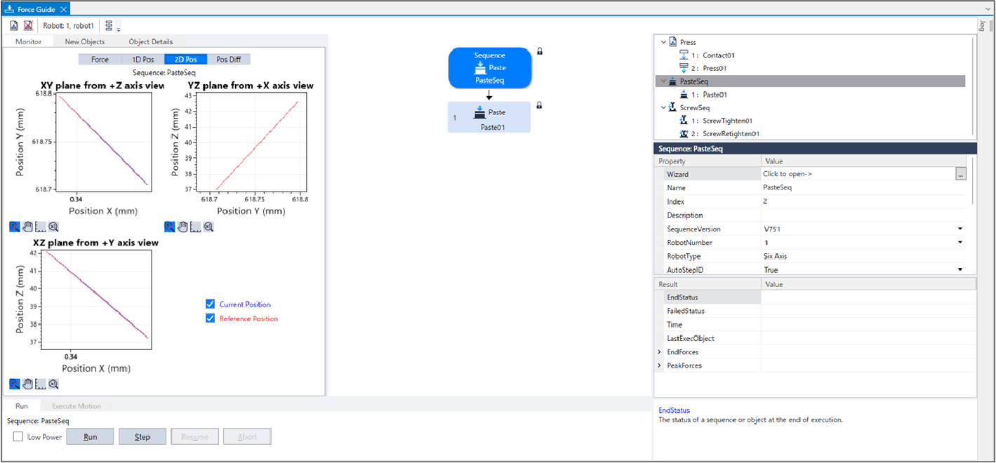
- Select the [Pos Diff] tab.
Record shifts by force control as relative position changes.
It is different from the graph on the [1D Pos] tab.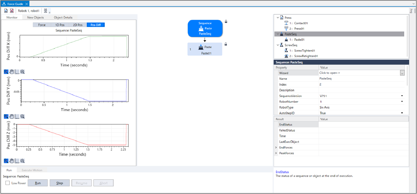
- Change the unit of the graph and check the changes of force or positions.
If it is not pasted correctly, the setting may not be correct.
Refer to the following and check the procedures of the tutorial.
- Whether a pressing force direction is correct
- Whether the setting of the approach distance is correct
- Whether the Tool setting is correct
Advanced Tasks
Let's do the following advanced tasks.
The default end condition for the Paste sequence position is whether the position of the object from the start of the Paste sequence is within "the approach distance ± 1mm".
By changing the end condition of the position, it may be possible to detect dimensional abnormalities of workpieces.
When the end condition of the position cannot be met, the sequence is determined to be failure and the operation ends.
Now try setting a failure condition.
Change the [Paste01] property as follows.
ItemValueDescriptionDistCheckTol 0.1 Specify the success condition range for distance moved from the motion start point.
Set the success condition range to "the approach distance ± 0.1mm".
Select the [Jog] tab to move the robot to the start point "P1".
To simulate that the height dimension of the workpiece being gripped is 0.5mm smaller, move the robot 0.5mm in the +Z direction from the start point "P1" in the [Jog] tab.
Now try running the sequence.
This ends the Paste sequence tutorial.