Part Feeder Object
KEY POINTS
Part feeding simulation is available only with Epson RC+ Standard Edition and Premium Edition. Refer to the following video manual for an overview and detailed instructions.
Sample connections and projects are provided for part feeding simulation. It is also used in the video manual mentioned above.
From the Epson RC+ 8.0 menu, select [Project]-[Open Project], then select [Projects]-[SimulatorDemos]-[PF_Sample_GX8_C], and then select [RC800 Series]–[PF Sample GX8-C] from the Epson RC+ 8.0 toolbar-[Connection:] list box. You can actually check the operations and behaviors described in the video manual.
When the parts feeder setting is enabled in [Setup]-[System Configuration]-[Controller]-[Part Feeder], the part feeder object is automatically displayed in the layout tree and 3D display.
This operation is available only with Epson RC+ Standard Edition and Premium Edition.
Feeder Object
This object represents the part feeder unit. Most of the attributes are the same as for Layout objects, but some attributes are only valid for part feeder objects.
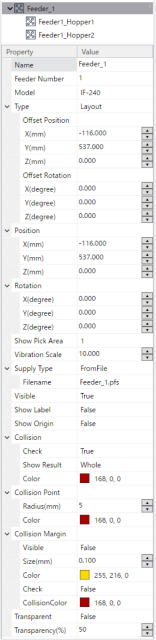
| Property | Value |
|---|---|
| Name | Displays the feeder name. You can specify any name. |
| Feeder Number | Displays the feeder number. This is the feeder number set in [Setup]-[System Configuration]-[Controller]-[Part Feeder]. It cannot be changed from the property grid. |
| Model | Displays the feeder model name. This is the feeder model name set in [Setup]-[System Configuration]-[Controller]-[Part Feeder]. For IF-380 and IF-530, a model can be selected according to the height of the frame surrounding the platform. For IF-A1520 and IF-A2330, when Purge gate installed is enabled, a model can be selected according to the purge gate mounting position (left or right). The 3D display changes according to the selected model. |
| Type | Setting fixed to "Layout". Cannot change the setting. |
| Offset Position | You can show/set the position of an object as an offset from its parent object. If no parent object exists, it is shown/set the same as the Position property. |
| Offset Rotation | You can show/set the placement angle of an object as an offset from its parent object. If the parent object does not exist, it will display/set the same as the Rotation property. |
| Position | Specifies the center point in simulator World coordinates. |
| Rotation | Specify the placement angle. |
| Show Pick Area | Specifies the part number for which the pick area is displayed. |
| SupplyType | Displays/Sets the parts supply method.
|
| Filename | When the SupplyType property is set to FromFile, specifies the file (parts supply file) in which the parts supply information is recorded. Clicking the  button displays the file open dialog. Specifies a parts supply file (extension: ".pfs"). button displays the file open dialog. Specifies a parts supply file (extension: ".pfs"). |
| Visible |
|
| Show Label |
|
| Show Origin |
|
For properties such as "Collision", "Collision Margin", or "Transparent", refer to the layout objects properties.
Hopper object
This object represents the hopper. When [Hopper installed] is enabled in [Setup]-[System Configuration]-[Controller]-[Part Feeder], it is automatically added as a child object of the feeder object. It cannot be used as a standalone object or as a child object of another object. Most of the attributes are the same as for Layout objects, but some attributes are only valid for hopper objects.
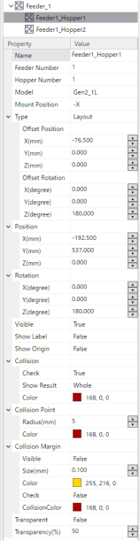
| Property | Value |
|---|---|
| Name | Displays the hopper name. You can specify any name. |
| Feeder Number | Displays the number of the feeder that is the parent object. It cannot be changed from the property grid. |
| Hopper Number | Displays the hopper number. Cannot change the setting. |
| Model | Displays the hopper model name. You can also select a model according to the hopper type selected in [Setup]-[System Configuration]-[Controller]-[Part Feeder]-[Hopper installed]. The 3D display changes according to the selected model. |
| Mount Position | Sets the hopper mounting position. Specifies the direction of the hopper supply port with respect to the origin coordinate system of the feeder unit. The hopper display in the 3D display changes according to the specified direction.
|
| Type | Setting fixed to "Layout". Cannot change the setting. |
| Offset Position | You can show/set the position of an object as an offset from the feeder unit, which is the parent object. |
| Offset Rotation | You can show/set the installation angle of an object as an offset from the feeder unit, which is the parent object. |
| Position | Specifies the center point in simulator World coordinates. |
| Rotation | Specify the placement angle. |
| Visible |
|
| Show Label |
|
| Show Origin |
|
For properties such as "Collision", "Collision Margin", or "Transparent", refer to the layout objects properties.
Feeder Control Panel
Select and right-click a feeder object or hopper object in the layout tree or 3D display to display the following context menu.
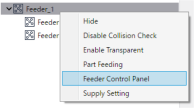
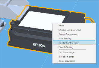
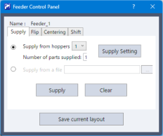
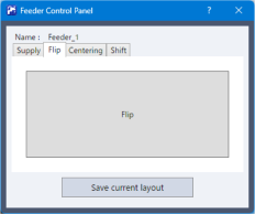
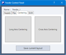
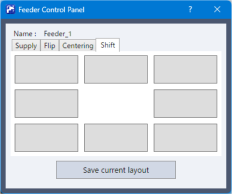
When you select "Feeder Control Panel", the following dialog box appears.
KEY POINTS
This function can be used to simulate feeder operation.
This simulation is intended to check the supply or placement state of parts on the feeder, and it reproduces the positions and orientations of parts in a simulated manner. This is a simulation based on a simplified model and does not perform strict physical simulation including feeder vibration, collision, or friction. Therefore, the behavior of the actual device is not completely reproduced. Use this function for preliminary verification purposes such as layout study and general operation checking.
| Item | Description |
|---|---|
| Name | Displays the name of the feeder object for which the operation is set. |
Supply Flip Centering Shift | Specifies the feeder operation.
|
| Save current layout | The part placement state after executing the feeder operation can be saved as a part placement file. |
| Supply from hoppers | Supplies the number of parts set in [Number of parts supplied] from the hopper with the specified number. Clicking the [Supply Setting] button allows you to specify the object used as the part. |
| Supply from a file | Uses a part placement file for parts supply. Clicking the button displays the file open dialog. Specifies a part placement file. |
| Supply | Supplies parts onto the feeder platform. |
| Clear | Removes parts from the feeder platform. |